Upper
Expo Arms 7075 Stripped AR-15 Upper Receiver
Expo Arms' stripped upper: a "Precision machined 7075-T6 aluminum forging" with "M4 feed ramp cuts" and a "MIL-SPEC Type III Class 2 hardcoat anodized finish", its rail unmarked ("T Marks: Unmarked"). It "Accepts MIL-SPEC upper parts" and "is compatible with standard mil-spec lowers, handguards, and barrels". "Port door and forward assist hardware not included".
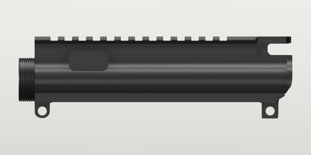
- Weight
- No weight on file yet: No page states one: Primary Arms' page for it (the brand owner's) has no weight row and none in its text, its T-marked sibling's page none, and no seller or reviewer on file gives a figure. Not estimated: a build with it says its total is unknown.
- Lowest price
- $49.99 at Primary Arms, read Nov 21, 2026 (Black)
- Maker's number
- XP-UPPER
- Colour
- Black (placeholder)
- Drawn as
- modelled
- Maker's page
- primaryarms.com
In “Budget 16 in carbine”, a build on the start page, as it is.
Its figures
Every figure the site draws and checks it by, with where it came from. Open one for each source's reading, and why one is used where they differ.
Weight (the stripped receiver: no port door, forward assist or barrel)No value yetMissingNo source yet
No page states one: Primary Arms' page for it (the brand owner's) has no weight row and none in its text, its T-marked sibling's page none, and no seller or reviewer on file gives a figure. Not estimated: a build with it says its total is unknown.
Bore axis above the takedown pin centre0.877 in ± 0.0015 in 22.3 mmConfirmedWorked out: {std.ar15.bore_axis_y}
Worked out 0.8775 in ± 0.0015 in used
{std.ar15.bore_axis_y}, harvested
The standard's. Primary Arms' page: "Accepts MIL-SPEC upper parts"; "It is compatible with standard mil-spec lowers, handguards, and barrels".
Photo 0.876 in ± 0.006 in
Primary Arms' XP-UPPER_02: the stripped receiver's right side, level, 2200 x 1467, harvested
Scale: its own lug holes, std.ar15.pin_spacing apart: each bore's near and far edges fitted as circles (rms 0.06 to 0.08 px), their midpoints the frame's points: 256.86 px/in on the receiver's mid-plane; the rail's 13 slots fit the standard pitch to 0.07% on it. Read by the threaded nose's top and bottom edges (y 1.492 and 0.260 over x 6.7 to 6.9: its silhouette's edges lie on the mid-plane from a level lens): their middle; ± is 1.5 px
The drawings' figure; this receiver's own photo puts its nose's axis within 0.002 of it.
The top rail's surface above the pin line2.092 in ± 0.008 in 53.1 mmCorroboratedPhoto: Primary Arms' XP-UPPER_02: the stripped receiver's right side, level, 2200 x 1467
Photo 2.092 in ± 0.008 in used
Primary Arms' XP-UPPER_02: the stripped receiver's right side, level, 2200 x 1467, harvested
Scale: its own lug holes, std.ar15.pin_spacing apart: each bore's near and far edges fitted as circles (rms 0.06 to 0.08 px), their midpoints the frame's points: 256.86 px/in on the receiver's mid-plane; the rail's 13 slots fit the standard pitch to 0.07% on it. Read by the rail's tooth tops along x 1.0 to 6.0 read 2.103 at mid-length (2.108 at the takedown hole, 2.098 at the pivot: the receiver is yawed 2 degrees, its rear nearer); the silhouette's top is the tooth's near edge, 0.31 to 0.42 nearer than the mid-plane: the lens stands about 36 in away opposite x 1.69, y 1.04 (right_photo_lens_*), so what is z nearer than the mid-plane reads large about that point by 36 / (36 - z), 0.011 less; ± is 1.5 px and that edge's place
Photo 2.09 in ± 0.02 in
Primary Arms' XP-UPPER_03: the stripped receiver's left side, from above, 2200 x 1467, harvested
Scale: its own lug holes, std.ar15.pin_spacing apart, each bore's near and far edges fitted as circles, their midpoints the frame's points: 254.51 px/in on the mid-plane at the pin line (the rail, nearer the lens from above, reads 0.71% larger by its slots' pitch). Read by the tooth tops read 2.106 at mid-length; from above the silhouette's top is the tooth's far edge and the rail 0.7% nearer the lens than the pin line (the lens stands about 35 in away opposite x 3.36 and some 5 in above the pin line (left_photo_lens_*)): 0.015 less, ± 0.01 for where the lens stood
The level view; the view from above agrees within its ±.
Read on Primary Arms' own two photos, each in the frame of its own lug holes. One reviewer on its page calls it "a high rise upper" whose rail "sticks up above the handguard": the catalog's other forged receiver reads 2.09 the same way (aero-m4e1-threaded-upper.rail_top_above_pin) and the reference model of a mil-spec forging has 2.090, so its rail stands where a mil-spec flat top's does.
The rearmost rail slot's centre ahead of the takedown pin1.314 in ± 0.008 in 33.4 mmCorroboratedPhoto: Primary Arms' XP-UPPER_02: the stripped receiver's right side, level, 2200 x 1467
Photo 1.314 in ± 0.008 in used
Primary Arms' XP-UPPER_02: the stripped receiver's right side, level, 2200 x 1467, harvested
Scale: its own lug holes, std.ar15.pin_spacing apart: each bore's near and far edges fitted as circles (rms 0.06 to 0.08 px), their midpoints the frame's points: 256.86 px/in on the receiver's mid-plane; the rail's 13 slots fit the standard pitch to 0.07% on it. Read by the top edge's 13 slot floors, their centres fitted to the standard pitch: 1.316 (rms 0.003; the pitch fits 0.3943), less 0.002 for the yaw; a slot's centre in the silhouette is its centre on the mid-plane
Photo 1.3 in ± 0.015 in
Primary Arms' XP-UPPER_03: the stripped receiver's left side, from above, 2200 x 1467, harvested
Scale: its own lug holes, std.ar15.pin_spacing apart, each bore's near and far edges fitted as circles, their midpoints the frame's points: 254.51 px/in on the mid-plane at the pin line (the rail, nearer the lens from above, reads 0.71% larger by its slots' pitch). Read by the 13 slot centres run 1.286 to 6.048, 0.7% wide about the image's middle (x 3.19): 1.300 to 6.028 at the pin line's scale
The level view; the view from above reads 0.014 less, within its ±.
How many rail slots13ProvisionalPhoto: Primary Arms' XP-UPPER_02: the stripped receiver's right side, level, 2200 x 1467
Photo 13 count used
Primary Arms' XP-UPPER_02: the stripped receiver's right side, level, 2200 x 1467, harvested
Scale: its own lug holes, std.ar15.pin_spacing apart: each bore's near and far edges fitted as circles (rms 0.06 to 0.08 px), their midpoints the frame's points: 256.86 px/in on the receiver's mid-plane; the rail's 13 slots fit the standard pitch to 0.07% on it. Read by counted along the top edge; the left photo shows the same 13
Behind the first is a solid run of rail over the charging handle's channel (from rail_rear_x), ahead of the last a long tooth to the front shoulder.
The top rail's head: where it begins ahead of the tongue, X (the app draws the head from here)0.416 in ± 0.006 in 10.6 mmProvisionalWorked out: {std.ar15.rail_tongue_shoulder_x}
Worked out 0.4165 in ± 0.006 in used
{std.ar15.rail_tongue_shoulder_x}, from the site owner
Until 2026-10-20 this was the rail's rearmost point (now rail_tongue_rear_x), and the app drew the head at its full width from there, square: the charging handle's T, cut round for a rounded rail end, stood in its corners. Behind this the rail is the standard's tongue (std.ar15.rail_tongue_*), which the receiver's model carries, as the 22RB's does.
The top rail's tongue: its rounded end's rearmost point, X ahead of the takedown pin-0.588 in ± 0.008 in -14.9 mmProvisionalPhoto: Primary Arms' XP-UPPER_02: the stripped receiver's right side, level, 2200 x 1467
Photo -0.588 in ± 0.008 in used
Primary Arms' XP-UPPER_02: the stripped receiver's right side, level, 2200 x 1467, harvested
Scale: its own lug holes, std.ar15.pin_spacing apart: each bore's near and far edges fitted as circles (rms 0.06 to 0.08 px), their midpoints the frame's points: 256.86 px/in on the receiver's mid-plane; the rail's 13 slots fit the standard pitch to 0.07% on it. Read by where the top edge first reaches the teeth's height (the tail's end is rounded in plan, as the three-quarter views show: its tip is on the mid-plane); the left photo reads -0.616 at the rail's 0.7% larger scale about x 3.19: -0.589
The top rail's front end ahead of the takedown pin6.591 in ± 0.011 in 167.4 mmConfirmedWorked out: {.front_face_x} - {std.ar15.upper_barrel_thread_length}
Worked out 6.591 in ± 0.011 in used
{.front_face_x} - {std.ar15.upper_barrel_thread_length}, harvested
The rail's last tooth ends flush with the body's front shoulder, where the barrel-nut thread begins (both photos): the drawing's .445 REF behind the front face.
Photo 6.59 in ± 0.012 in
Primary Arms' XP-UPPER_02: the stripped receiver's right side, level, 2200 x 1467, harvested
Scale: its own lug holes, std.ar15.pin_spacing apart: each bore's near and far edges fitted as circles (rms 0.06 to 0.08 px), their midpoints the frame's points: 256.86 px/in on the receiver's mid-plane; the rail's 13 slots fit the standard pitch to 0.07% on it. Read by the silhouette's front edge at the rail's height reads 6.640; it is the shoulder's near edge, about 0.37 nearer than the mid-plane: the lens stands about 36 in away opposite x 1.69, y 1.04 (right_photo_lens_*), so what is z nearer than the mid-plane reads large about that point by 36 / (36 - z), 0.050 less
The drawing's shoulder; the photo's edge lands on it.
Ahead of it the receiver is the barrel nut's thread.
The receiver's rear face behind the takedown pin (negative)-0.621 in ± 0.005 in -15.8 mmConfirmedWorked out: {std.ar15.upper_rear_face_x}
Worked out -0.621 in ± 0.005 in used
{std.ar15.upper_rear_face_x}, harvested
The Army's drawing of the upper (8448524). Primary Arms' page: "Accepts MIL-SPEC upper parts"; "It is compatible with standard mil-spec lowers, handguards, and barrels".
Photo -0.625 in ± 0.012 in
Primary Arms' XP-UPPER_03: the stripped receiver's left side, from above, 2200 x 1467, harvested
Scale: its own lug holes, std.ar15.pin_spacing apart, each bore's near and far edges fitted as circles, their midpoints the frame's points: 254.51 px/in on the mid-plane at the pin line (the rail, nearer the lens from above, reads 0.71% larger by its slots' pitch). Read by the silhouette's rear edge at y 1.5 to 1.8, the flat left side's rear corner (z 0.32 nearer than the mid-plane), reads -0.682: 0.021 less for the scale at that height, 0.036 less for the near edge (the lens stands about 35 in away opposite x 3.36 and some 5 in above the pin line (left_photo_lens_*))
Photo -0.636 in ± 0.02 in
Primary Arms' XP-UPPER_02: the stripped receiver's right side, level, 2200 x 1467, harvested
Scale: its own lug holes, std.ar15.pin_spacing apart: each bore's near and far edges fitted as circles (rms 0.06 to 0.08 px), their midpoints the frame's points: 256.86 px/in on the receiver's mid-plane; the rail's 13 slots fit the standard pitch to 0.07% on it. Read by the silhouette's rear edge at y 1.45 to 1.62 reads -0.666 where the forward assist's housing joins the wall; taken as an edge 0.32 nearer than the mid-plane it is -0.645, at 0.6 nearer -0.627: ± covers that
The drawing dimensions the face; both photos agree with it within their ±.
The receiver's front face (the end of its barrel-nut thread) ahead of the takedown pin7.036 in ± 0.005 in 178.7 mmConfirmedWorked out: {std.ar15.upper_front_face_x}
Worked out 7.036 in ± 0.005 in used
{std.ar15.upper_front_face_x}, harvested
The Army's drawing: .661 ahead of the pivot lug's hole. Primary Arms' page: "Accepts MIL-SPEC upper parts"; "It is compatible with standard mil-spec lowers, handguards, and barrels".
Photo 7.029 in ± 0.012 in
Primary Arms' XP-UPPER_02: the stripped receiver's right side, level, 2200 x 1467, harvested
Scale: its own lug holes, std.ar15.pin_spacing apart: each bore's near and far edges fitted as circles (rms 0.06 to 0.08 px), their midpoints the frame's points: 256.86 px/in on the receiver's mid-plane; the rail's 13 slots fit the standard pitch to 0.07% on it. Read by the silhouette's front tip reads 7.121: the thread's near rim, 0.62 nearer than the mid-plane and 5.4 in from where the lens stands: the lens stands about 36 in away opposite x 1.69, y 1.04 (right_photo_lens_*), so what is z nearer than the mid-plane reads large about that point by 36 / (36 - z), 0.093 less (the rim's arc sags 0.09 there, as that angle makes it)
Photo 7.034 in ± 0.012 in
Primary Arms' XP-UPPER_03: the stripped receiver's left side, from above, 2200 x 1467, harvested
Scale: its own lug holes, std.ar15.pin_spacing apart, each bore's near and far edges fitted as circles, their midpoints the frame's points: 254.51 px/in on the mid-plane at the pin line (the rail, nearer the lens from above, reads 0.71% larger by its slots' pitch). Read by the tip reads 7.113: 0.012 less for the scale at the bore's height, 0.066 less for the near rim (the lens stands about 35 in away opposite x 3.36 and some 5 in above the pin line (left_photo_lens_*))
The drawing dimensions the face; both photos land on it within their ±.
The receiver's underside above the pin line0.248 in ± 0.0015 in 6.3 mmConfirmedWorked out: {std.ar15.deck_y}
Worked out 0.2485 in ± 0.0015 in used
{std.ar15.deck_y}, harvested
It sits on the lower's deck.
Photo 0.25 in ± 0.008 in
Primary Arms' XP-UPPER_02: the stripped receiver's right side, level, 2200 x 1467, harvested
Scale: its own lug holes, std.ar15.pin_spacing apart: each bore's near and far edges fitted as circles (rms 0.06 to 0.08 px), their midpoints the frame's points: 256.86 px/in on the receiver's mid-plane; the rail's 13 slots fit the standard pitch to 0.07% on it. Read by the silhouette's lower edge between the lugs reads 0.238 to 0.246: the wall's near lower edge, 0.45 nearer than the mid-plane and 0.8 below where the lens stands: the lens stands about 36 in away opposite x 1.69, y 1.04 (right_photo_lens_*), so what is z nearer than the mid-plane reads large about that point by 36 / (36 - z), 0.010 more
The lower's deck; the photo's edge lands on it.
Width of the receiver's body1.18 in ± 0.02 in 30 mmConfirmedStandard: US Army TDP drawing 8448524 (Receiver, Upper), sheet 2 of 2, rev G: View G-G; user-supplied scan (Distribution Statement F, Colt proprietary notice), a copy on file
Standard “FORGED DIA 1.18 DIA REF -V-” used
US Army TDP drawing 8448524 (Receiver, Upper), sheet 2 of 2, rev G: View G-G; user-supplied scan (Distribution Statement F, Colt proprietary notice), a copy on file, from the site owner
The round body just behind the threaded nose, as aero-m4e1-threaded-upper.width reads it. Not measured on this receiver: no end or top view of it is on file.
The mil-spec forging's: its page calls it a "Precision machined 7075-T6 aluminum forging" that "Accepts MIL-SPEC upper parts". Its forward assist's housing and brass deflector stand out past it on the right.
The charging handle's channel above the bore's axis0.856 in ± 0.007 in 21.8 mmConfirmedWorked out: {std.ar15.charging_handle_axis_y} - {.bore_axis_above_pin}
Photo 0.87 in ± 0.05 in
Primary Arms' XP-UPPER_02: the stripped receiver's right side, level, 2200 x 1467, harvested
Scale: its own lug holes, std.ar15.pin_spacing apart: each bore's near and far edges fitted as circles (rms 0.06 to 0.08 px), their midpoints the frame's points: 256.86 px/in on the receiver's mid-plane; the rail's 13 slots fit the standard pitch to 0.07% on it. Read by the notch in the traced outline's rear end, from the wall's top at 1.595 to the rail's tail's underside at 1.894: its middle less the bore's 0.8775
Worked out 0.8563 in ± 0.007 in used
{std.ar15.charging_handle_axis_y} - {.bore_axis_above_pin}, from the site owner
Riding on its guide lugs on the channel's tier: std.ar15.charging_handle_axis_y.
A handle rides on its guide lugs on the channel's tier (std.ar15.charging_handle_axis_y, the Army's drawing's); the photo reads the see-through notch's middle, which is the room the handle's block lies in, and agrees within its ±.
The notch the handle's latch end lies in: the handle lies at its height (as aero-m4e1-threaded-upper.charging_handle_above_bore).
The charging handle's seat: the front wall of the open notch under the rail's rear end, ahead of the takedown pin0.069 in ± 0.02 in 1.8 mmCorroboratedPhoto: Primary Arms' XP-UPPER_02: the stripped receiver's right side, level, 2200 x 1467
Photo 0.069 in ± 0.02 in used
Primary Arms' XP-UPPER_02: the stripped receiver's right side, level, 2200 x 1467, harvested
Scale: its own lug holes, std.ar15.pin_spacing apart: each bore's near and far edges fitted as circles (rms 0.06 to 0.08 px), their midpoints the frame's points: 256.86 px/in on the receiver's mid-plane; the rail's 13 slots fit the standard pitch to 0.07% on it. Read by the see-through notch's front wall in the traced outline (profiles.side): its flat at x 0.069 from y 1.675 to 1.83, between two corners cut back to x 0.013 and -0.014. What shows through a notch is bounded by the wall's near edge, 0.32 to 0.45 nearer than the mid-plane (the flat side, or the rail's foot): the lens stands about 36 in away opposite x 1.69 (right_photo_lens_*), so that edge reads 0.015 to 0.020 behind the wall itself, which would be at 0.084 to 0.089; ± covers it
Photo 0.045 in ± 0.03 in
Primary Arms' XP-UPPER_03: the stripped receiver's left side, from above, 2200 x 1467, harvested
Scale: its own lug holes, std.ar15.pin_spacing apart, each bore's near and far edges fitted as circles, their midpoints the frame's points: 254.51 px/in on the mid-plane at the pin line (the rail, nearer the lens from above, reads 0.71% larger by its slots' pitch). Read by the same wall in the left outline (profiles.left): x 0.043 to 0.047 from y 1.631 to 1.781. The near edge again, the lens about 35 in away opposite x 3.36 (left_photo_lens_*): it reads 0.03 to 0.04 behind the wall itself, which would be at 0.076 to 0.088; ± covers it
Standard 0.075 in ± 0.015 in
US Army TDP drawing 8448524 (Receiver, Upper), sheet 1 of 2, rev G: side elevation, scaled (the notch has no callout in this view); user-supplied scan (Distribution Statement F, Colt proprietary notice), a copy on file, from the site owner
Scaled, not a callout. On the 6600 px scan the two lug holes, fitted as circles, are 1966 px apart (308.4 px/in over std.ar15.pin_spacing) and the notch's front wall (column 2427.5) is 21.5 px ahead of the takedown hole's centre: 0.070. From the rear face's line, 217 px behind the wall, it is 0.083: the drawing dimensions that face at -0.621 and the scan has it at -0.634 by the holes. Between the two; ± covers both. The notch is 0.31 to 0.32 high there, for the handle's .2985 (drawing 8448518), its front corners cut back 0.06.
This receiver's own notch in the outline its model is built from, where the model's wall is: a handle seated there stands in nothing. The Army's drawing, scaled, reads 0.006 more, and the left photo 0.024 less by its nearer edge; all three within their ±.
Where a charging handle stops. The notch is cut across the receiver under the rail's rear end and is open to the rear: the handle's block (its T ahead of the wings or latches, as thick as the shaft) lies in it with its shoulder against this wall, and the shaft runs on through the slot ahead of it. Until 2026-10-05 the handle was placed with its shoulder at the rear face, 0.69 in behind this (that day's review of the models: its whole T hung behind the receiver, over the castle nut, its latch's hook 0.6 in behind the slot traced for it on this receiver's left side, latch_slot in profiles.left: x 0.198 to 0.371). Magpul's photo of a handle in a receiver (a copy on file) has it so: the T's wing astride the rear face, the notch filled to its front wall.
The right side photo: its lens's distance from the receiver's mid-plane36 in ± 2 in 914.4 mmProvisionalPhoto: Primary Arms' XP-UPPER_02: the stripped receiver's right side, level, 2200 x 1467
Photo 36 in ± 2 in used
Primary Arms' XP-UPPER_02: the stripped receiver's right side, level, 2200 x 1467, harvested
Scale: its own lug holes, std.ar15.pin_spacing apart: each bore's near and far edges fitted as circles (rms 0.06 to 0.08 px), their midpoints the frame's points: 256.86 px/in on the receiver's mid-plane; the rail's 13 slots fit the standard pitch to 0.07% on it. Read by the two bores' far edges are 1626.2 px apart and their near ones 1648.7: the far faces of the lugs are 1.384% further than the near ones, 0.4945 behind them (lug_width): 35.7 in to the near faces. The rail's pitch on the near faces' scale (0.9938 of the standard) gives 40 +3/-3; ± covers both
A property of Primary Arms' photo aad70ef8abd5, not of the receiver: the model corrects what the right side shows nearer the lens (the forward assist's housing, the deflector, the hinge lugs) by it.
The right side photo: where its lens stands, X1.69 in ± 0.1 in 42.9 mmProvisionalPhoto: Primary Arms' XP-UPPER_02: the stripped receiver's right side, level, 2200 x 1467
Photo 1.69 in ± 0.1 in used
Primary Arms' XP-UPPER_02: the stripped receiver's right side, level, 2200 x 1467, harvested
Scale: its own lug holes, std.ar15.pin_spacing apart: each bore's near and far edges fitted as circles (rms 0.06 to 0.08 px), their midpoints the frame's points: 256.86 px/in on the receiver's mid-plane; the rail's 13 slots fit the standard pitch to 0.07% on it. Read by each bore's far edge sits off its near one toward the point the lens is opposite: +5.9, -3.6 px at the takedown hole, -16.6, -3.7 px at the pivot; the two lines meet at px (708, 708). The thread's rim sags 0.09 at the front as that makes it, and the rail's teeth show their rear faces ahead of about x 2
The right side photo: where its lens stands, Y1.04 in ± 0.1 in 26.4 mmProvisionalPhoto: Primary Arms' XP-UPPER_02: the stripped receiver's right side, level, 2200 x 1467
Photo 1.04 in ± 0.1 in used
Primary Arms' XP-UPPER_02: the stripped receiver's right side, level, 2200 x 1467, harvested
Scale: its own lug holes, std.ar15.pin_spacing apart: each bore's near and far edges fitted as circles (rms 0.06 to 0.08 px), their midpoints the frame's points: 256.86 px/in on the receiver's mid-plane; the rail's 13 slots fit the standard pitch to 0.07% on it. Read by as right_photo_lens_x: px row 708, level with the bore
The left side photo: its lens's distance from the receiver's mid-plane34.8 in ± 2 in 883.9 mmProvisionalPhoto: Primary Arms' XP-UPPER_03: the stripped receiver's left side, from above, 2200 x 1467
Photo 34.8 in ± 2 in used
Primary Arms' XP-UPPER_03: the stripped receiver's left side, from above, 2200 x 1467, harvested
Scale: its own lug holes, std.ar15.pin_spacing apart, each bore's near and far edges fitted as circles, their midpoints the frame's points: 254.51 px/in on the mid-plane at the pin line (the rail, nearer the lens from above, reads 0.71% larger by its slots' pitch). Read by the bores' far edges are 1611.0 px apart and their near ones 1634.0: 1.430% over the lugs' 0.4945 (lug_width)
A property of Primary Arms' photo 8888fc8d0ccb.
The left side photo: where its lens stands, X3.36 in ± 0.1 in 85.3 mmProvisionalPhoto: Primary Arms' XP-UPPER_03: the stripped receiver's left side, from above, 2200 x 1467
Photo 3.36 in ± 0.1 in used
Primary Arms' XP-UPPER_03: the stripped receiver's left side, from above, 2200 x 1467, harvested
Scale: its own lug holes, std.ar15.pin_spacing apart, each bore's near and far edges fitted as circles, their midpoints the frame's points: 254.51 px/in on the mid-plane at the pin line (the rail, nearer the lens from above, reads 0.71% larger by its slots' pitch). Read by each bore's far edge sits off its near one toward that point: -12.1, -19.7 px at the takedown hole, +10.9, -17.4 px at the pivot
The left side photo: where its lens stands, Y4.8 in ± 0.5 in 121.9 mmProvisionalPhoto: Primary Arms' XP-UPPER_03: the stripped receiver's left side, from above, 2200 x 1467
Photo 4.8 in ± 0.5 in used
Primary Arms' XP-UPPER_03: the stripped receiver's left side, from above, 2200 x 1467, harvested
Scale: its own lug holes, std.ar15.pin_spacing apart, each bore's near and far edges fitted as circles, their midpoints the frame's points: 254.51 px/in on the mid-plane at the pin line (the rail, nearer the lens from above, reads 0.71% larger by its slots' pitch). Read by as left_photo_lens_x: the two holes' offsets put it 4.8 and 5.5 above the pin line; the rail's top and the underside's edge, read against the right photo's, fit 4.4
The round body's radius about the bore (the forging's)0.59 in ± 0.01 in 15 mmConfirmedStandard: US Army TDP drawing 8448524 (Receiver, Upper), sheet 2 of 2, rev G: View G-G; user-supplied scan (Distribution Statement F, Colt proprietary notice), a copy on file
Standard “FORGED DIA 1.18 DIA REF -V-” used
US Army TDP drawing 8448524 (Receiver, Upper), sheet 2 of 2, rev G: View G-G; user-supplied scan (Distribution Statement F, Colt proprietary notice), a copy on file, from the site owner
Model 0.6 in ± 0.003 in
the AR-15 CAD reference set the user supplied, Deterrence Dispensed V11: a third-party model of a mil-spec forging, from the site owner
Read by its faces read from the STEP text in the rifle frame its lug holes set (x = 15.0189 - mx, y = my + 6.2992, z = -(mz + 0.8128), inches; a working script): cylindrical faces r 0.6000 about the bore's axis, x -0.43 to 6.59
The drawing's forged figure; the model's is 0.01 more.
The bore the bolt carrier runs in1 in ± 0.002 in 25.4 mmConfirmedStandard: US Army TDP drawing 8448524 (Receiver, Upper), sheet 1 of 2, rev G: note 4; user-supplied scan (Distribution Statement F, Colt proprietary notice), a copy on file
Standard “DIA -P- (IN 1.000 DIA ±.002 AREA)” used
US Army TDP drawing 8448524 (Receiver, Upper), sheet 1 of 2, rev G: note 4; user-supplied scan (Distribution Statement F, Colt proprietary notice), a copy on file, from the site owner
The rail's dovetail, its foot (where the neck begins), Y above the pin line1.885 in ± 0.003 in 47.9 mmCorroboratedModel: the AR-15 CAD reference set the user supplied, Deterrence Dispensed V11: a third-party model of a mil-spec forging
Model 1.885 in ± 0.003 in used
the AR-15 CAD reference set the user supplied, Deterrence Dispensed V11: a third-party model of a mil-spec forging, from the site owner
Read by its faces read from the STEP text in the rifle frame its lug holes set (x = 15.0189 - mx, y = my + 6.2992, z = -(mz + 0.8128), inches; a working script): the planes under the dovetail at y 1.885, z 0.309 to 0.333
Photo 1.888 in ± 0.01 in
Primary Arms' XP-UPPER_02: the stripped receiver's right side, level, 2200 x 1467, harvested
Scale: its own lug holes, std.ar15.pin_spacing apart: each bore's near and far edges fitted as circles (rms 0.06 to 0.08 px), their midpoints the frame's points: 256.86 px/in on the receiver's mid-plane; the rail's 13 slots fit the standard pitch to 0.07% on it. Read by the dark line under the rail, px row 487 at u 700: 1.895, an edge 0.33 nearer than the mid-plane: the lens stands about 36 in away opposite x 1.69, y 1.04 (right_photo_lens_*), so what is z nearer than the mid-plane reads large about that point by 36 / (36 - z)
The model's face; this receiver's photo agrees within its ±.
The rail's dovetail at its foot, half its width0.321 in ± 0.013 in 8.2 mmCorroboratedWorked out: {std.picatinny.bevel_width} / 2 + {std.picatinny.lower_gauge_below_top} - ({.rail_top_above_pin} - {.dovetail_foot_y})
Model 0.333 in ± 0.003 in
the AR-15 CAD reference set the user supplied, Deterrence Dispensed V11: a third-party model of a mil-spec forging, from the site owner
Read by its faces read from the STEP text in the rifle frame its lug holes set (x = 15.0189 - mx, y = my + 6.2992, z = -(mz + 0.8128), inches; a working script): the planes at y 1.885 reach z 0.333
Worked out 0.321 in ± 0.013 in used
{std.picatinny.bevel_width} / 2 + {std.picatinny.lower_gauge_below_top} - ({.rail_top_above_pin} - {.dovetail_foot_y}), harvested
The standard's lower face carried on at its 45 degrees from the lower gauge line (.748 across, .154 below the rail's top) to the height the reference model has the foot at: the face every other rail on file has (the teeth the app draws on this body, a handguard's own rail) and every clamp's channel is cut to. ± is the gauge line's .010 and the model's .003.
The standard's, since 2026-10-12: a rail's head is MIL-STD-1913's, and the clamps' channels are cut to it (pipeline/blender/lib.py rail_seat). The reference model draws the same face a hundredth further out, at the standard's stated .164 where the ledger has the middle of .164 -.020 (std.picatinny.lower_gauge_below_top): inside the standard's band, and on a body drawn so every clamp stood 0.008 in into the rail along both sides (0.001 cubic inches of an Aimpoint's base). The model isn't authoritative beside the standard; its neck and the foot's height are still its own.
The rail's neck below its dovetail, half its width0.309 in ± 0.003 in 7.8 mmProvisionalModel: the AR-15 CAD reference set the user supplied, Deterrence Dispensed V11: a third-party model of a mil-spec forging
Model 0.309 in ± 0.003 in used
the AR-15 CAD reference set the user supplied, Deterrence Dispensed V11: a third-party model of a mil-spec forging, from the site owner
Read by its faces read from the STEP text in the rifle frame its lug holes set (x = 15.0189 - mx, y = my + 6.2992, z = -(mz + 0.8128), inches; a working script): the planes at y 1.700 and 1.885 begin at z 0.309
The rail's neck, where it meets the receiver's sides, Y1.7 in ± 0.003 in 43.2 mmCorroboratedModel: the AR-15 CAD reference set the user supplied, Deterrence Dispensed V11: a third-party model of a mil-spec forging
Model 1.7 in ± 0.003 in used
the AR-15 CAD reference set the user supplied, Deterrence Dispensed V11: a third-party model of a mil-spec forging, from the site owner
Read by its faces read from the STEP text in the rifle frame its lug holes set (x = 15.0189 - mx, y = my + 6.2992, z = -(mz + 0.8128), inches; a working script): the planes at y 1.700, z 0.309 to 0.319
Photo 1.698 in ± 0.01 in
Primary Arms' XP-UPPER_02: the stripped receiver's right side, level, 2200 x 1467, harvested
Scale: its own lug holes, std.ar15.pin_spacing apart: each bore's near and far edges fitted as circles (rms 0.06 to 0.08 px), their midpoints the frame's points: 256.86 px/in on the receiver's mid-plane; the rail's 13 slots fit the standard pitch to 0.07% on it. Read by the line along the side under the rail's neck, px row 536 at u 700: 1.704, an edge 0.32 nearer than the mid-plane: the lens stands about 36 in away opposite x 1.69, y 1.04 (right_photo_lens_*), so what is z nearer than the mid-plane reads large about that point by 36 / (36 - z)
The model's face; this receiver's photo agrees within its ±.
The receiver's sides below the rail's neck, half its width0.319 in ± 0.003 in 8.1 mmProvisionalModel: the AR-15 CAD reference set the user supplied, Deterrence Dispensed V11: a third-party model of a mil-spec forging
Model 0.319 in ± 0.003 in used
the AR-15 CAD reference set the user supplied, Deterrence Dispensed V11: a third-party model of a mil-spec forging, from the site owner
Read by its faces read from the STEP text in the rifle frame its lug holes set (x = 15.0189 - mx, y = my + 6.2992, z = -(mz + 0.8128), inches; a working script): the planes at y 1.700 end at z 0.319; a .10 fillet below them
The receiver's sides, where they turn into the round body, Y1.44 in ± 0.005 in 36.6 mmProvisionalModel: the AR-15 CAD reference set the user supplied, Deterrence Dispensed V11: a third-party model of a mil-spec forging
Model 1.44 in ± 0.005 in used
the AR-15 CAD reference set the user supplied, Deterrence Dispensed V11: a third-party model of a mil-spec forging, from the site owner
Read by its faces read from the STEP text in the rifle frame its lug holes set (x = 15.0189 - mx, y = my + 6.2992, z = -(mz + 0.8128), inches; a working script): the r .10 fillet between the flat side and the round body, its axis at y 1.440, z 0.419
The walls below the round body down to the underside, half the width0.453 in ± 0.003 in 11.5 mmProvisionalModel: the AR-15 CAD reference set the user supplied, Deterrence Dispensed V11: a third-party model of a mil-spec forging
Model 0.453 in ± 0.003 in used
the AR-15 CAD reference set the user supplied, Deterrence Dispensed V11: a third-party model of a mil-spec forging, from the site owner
Read by its faces read from the STEP text in the rifle frame its lug holes set (x = 15.0189 - mx, y = my + 6.2992, z = -(mz + 0.8128), inches; a working script): the r .075 fillets at y 0.458, their axes at z 0.528
The flange round the rear end, its radius about the bore0.694 in ± 0.003 in 17.6 mmProvisionalModel: the AR-15 CAD reference set the user supplied, Deterrence Dispensed V11: a third-party model of a mil-spec forging
Model 0.6938 in ± 0.003 in used
the AR-15 CAD reference set the user supplied, Deterrence Dispensed V11: a third-party model of a mil-spec forging, from the site owner
Read by its faces read from the STEP text in the rifle frame its lug holes set (x = 15.0189 - mx, y = my + 6.2992, z = -(mz + 0.8128), inches; a working script): cylindrical faces r 0.6938 about the bore's axis from the rear face to x -0.470, on both sides
The raised lip that follows the rear end's contour: the left photo shows it, its front edge about 0.2 ahead of the rear face.
The rear flange's front face, X-0.47 in ± 0.005 in -11.9 mmProvisionalModel: the AR-15 CAD reference set the user supplied, Deterrence Dispensed V11: a third-party model of a mil-spec forging
Model -0.47 in ± 0.005 in used
the AR-15 CAD reference set the user supplied, Deterrence Dispensed V11: a third-party model of a mil-spec forging, from the site owner
Read by its faces read from the STEP text in the rifle frame its lug holes set (x = 15.0189 - mx, y = my + 6.2992, z = -(mz + 0.8128), inches; a working script): the r 0.6938 faces end at x -0.470
The takedown and pivot lugs' width0.494 in ± 0.0015 in 12.6 mmConfirmedStandard: US Army TDP drawing 8448524 (Receiver, Upper), sheet 1 of 2, rev G: the rear elevation; user-supplied scan (Distribution Statement F, Colt proprietary notice), a copy on file
Standard “.496 -.003 BOTH LUGS” used
US Army TDP drawing 8448524 (Receiver, Upper), sheet 1 of 2, rev G: the rear elevation; user-supplied scan (Distribution Statement F, Colt proprietary notice), a copy on file, from the site owner
The reference model has them 0.494.
The takedown lug's rear face, how high it rises into the body, Y0.458 in ± 0.005 in 11.6 mmProvisionalModel: the AR-15 CAD reference set the user supplied, Deterrence Dispensed V11: a third-party model of a mil-spec forging
Model 0.458 in ± 0.005 in used
the AR-15 CAD reference set the user supplied, Deterrence Dispensed V11: a third-party model of a mil-spec forging, from the site owner
Read by its faces read from the STEP text in the rifle frame its lug holes set: the plane x -0.236 from y -0.212 to 0.458; the r .75 corner faces lie outside z ±0.247
Behind it the body's lower rear is cut away either side of the lug's width, to the arc a lower's rear walls rise along (std.ar15.rear_wall_arc_r; the upper's own is std.ar15.upper_rear_corner_r).
The lugs' pin holes0.251 in ± 0.001 in 6.4 mmConfirmedStandard: US Army TDP drawing 8448524 (Receiver, Upper), sheet 1 of 2, rev G: side elevation; user-supplied scan (Distribution Statement F, Colt proprietary notice), a copy on file
Standard “.250 DIA +.002 THRU (the takedown lug's, CSK .31 DIA X 90 INCL THIS SIDE ONLY); .250 DIA +.001 THRU (the pivot lug's)” used
US Army TDP drawing 8448524 (Receiver, Upper), sheet 1 of 2, rev G: side elevation; user-supplied scan (Distribution Statement F, Colt proprietary notice), a copy on file, from the site owner
Both photos' holes read 0.254 to 0.256 across on the near faces' scale.
The barrel-nut thread's major diameter1.244 in ± 0.0044 in 31.6 mmConfirmedStandard: US Army TDP drawing 8448524 (Receiver, Upper), sheet 1 of 2, rev G: plan view, the threaded end; user-supplied scan (Distribution Statement F, Colt proprietary notice), a copy on file
Standard “1 1/4 -18 UNEF-2A MAJOR DIA - 1.2485/1.2398 (AFTER ANODIZE)” used
US Army TDP drawing 8448524 (Receiver, Upper), sheet 1 of 2, rev G: plan view, the threaded end; user-supplied scan (Distribution Statement F, Colt proprietary notice), a copy on file, from the site owner
Photo 1.232 in ± 0.012 in
Primary Arms' XP-UPPER_02: the stripped receiver's right side, level, 2200 x 1467, harvested
Scale: its own lug holes, std.ar15.pin_spacing apart: each bore's near and far edges fitted as circles (rms 0.06 to 0.08 px), their midpoints the frame's points: 256.86 px/in on the receiver's mid-plane; the rail's 13 slots fit the standard pitch to 0.07% on it. Read by the nose's top to its bottom over x 6.7 to 6.9: 1.232; a black thread on white reads thin, its crests' tips lost
The drawing's thread, which its page's "compatible with standard mil-spec ... handguards, and barrels" makes this one's; the photo reads 1% under, as a black tube does on white.
The barrel-nut thread's minor diameter1.18 in ± 0.003 in 30 mmConfirmedStandard: US Army TDP drawing 8448524 (Receiver, Upper), sheet 1 of 2, rev G: plan view, the threaded end; user-supplied scan (Distribution Statement F, Colt proprietary notice), a copy on file
Standard “MINOR DIA - 1.1803 MAX” used
US Army TDP drawing 8448524 (Receiver, Upper), sheet 1 of 2, rev G: plan view, the threaded end; user-supplied scan (Distribution Statement F, Colt proprietary notice), a copy on file, from the site owner
The barrel-nut thread's turns to the inch18ConfirmedStandard: US Army TDP drawing 8448524 (Receiver, Upper), sheet 1 of 2, rev G: plan view, the threaded end; user-supplied scan (Distribution Statement F, Colt proprietary notice), a copy on file
Standard “1 1/4 -18 UNEF-2A” used
US Army TDP drawing 8448524 (Receiver, Upper), sheet 1 of 2, rev G: plan view, the threaded end; user-supplied scan (Distribution Statement F, Colt proprietary notice), a copy on file, from the site owner
The gas tube's hole in the front shoulder0.183 in ± 0.0015 in 4.7 mmConflictStandard: US Army TDP drawing 8448524 (Receiver, Upper), sheet 2 of 2, rev G: View F-F; user-supplied scan (Distribution Statement F, Colt proprietary notice), a copy on file
Standard “.182 DIA +.003 THRU; .312 DIA +.010 BACK BORE” used
US Army TDP drawing 8448524 (Receiver, Upper), sheet 2 of 2, rev G: View F-F; user-supplied scan (Distribution Statement F, Colt proprietary notice), a copy on file, from the site owner
Model 0.175 in ± 0.003 in
the AR-15 CAD reference set the user supplied, Deterrence Dispensed V11: a third-party model of a mil-spec forging, from the site owner
Read by its faces read from the STEP text in the rifle frame its lug holes set (x = 15.0189 - mx, y = my + 6.2992, z = -(mz + 0.8128), inches; a working script): a cylinder r 0.0875 along x at y 1.662, z 0 (0.783 above the bore), x 6.401 to 6.591
The drawing's callout; the model's hole is 0.008 smaller.
tdp and model differ by 0.009 in beyond what each states it is good to.
Above the thread on the bore's mid-plane, std.ar15.gas_tube_above_bore above the bore. Primary Arms' three-quarter photo (5da4e9e47f7d) shows it with four small reliefs at its corners.
The gas tube hole's four corner reliefs, diameter0.094 in ± 0.002 in 2.4 mmConfirmedStandard: US Army TDP drawing 8448524 (Receiver, Upper), sheet 2 of 2, rev G: View F-F; user-supplied scan (Distribution Statement F, Colt proprietary notice), a copy on file
Standard “.047 R, 4 PLACES EQUALLY SPACED RANDOM ORIENTATION EXCEPT MUST NOT INTERSECT THREADS” used
US Army TDP drawing 8448524 (Receiver, Upper), sheet 2 of 2, rev G: View F-F; user-supplied scan (Distribution Statement F, Colt proprietary notice), a copy on file, from the site owner
Model 0.09 in ± 0.003 in
the AR-15 CAD reference set the user supplied, Deterrence Dispensed V11: a third-party model of a mil-spec forging, from the site owner
Read by its faces read from the STEP text in the rifle frame its lug holes set (x = 15.0189 - mx, y = my + 6.2992, z = -(mz + 0.8128), inches; a working script): four cylinders r 0.0450 along x round the gas tube's hole
The drawing's radius; the model's is 0.002 less.
The gas tube hole's corner reliefs, off its centre each way0.078 in ± 0.003 in 2 mmProvisionalModel: the AR-15 CAD reference set the user supplied, Deterrence Dispensed V11: a third-party model of a mil-spec forging
Model 0.078 in ± 0.003 in used
the AR-15 CAD reference set the user supplied, Deterrence Dispensed V11: a third-party model of a mil-spec forging, from the site owner
Read by its faces read from the STEP text in the rifle frame its lug holes set (x = 15.0189 - mx, y = my + 6.2992, z = -(mz + 0.8128), inches; a working script): their axes at y 1.585 and 1.740, z ±0.078: 0.0775 and 0.078 off the hole's centre
The ejection port's length3.125 in ± 0.005 in 79.4 mmConflictStandard: US Army TDP drawing 8448524 (Receiver, Upper), sheet 1 of 2, rev G: side elevation; user-supplied scan (Distribution Statement F, Colt proprietary notice), a copy on file
Standard “3.125; .25 R TRUE 2 PLACES; 1.562 ±.010” used
US Army TDP drawing 8448524 (Receiver, Upper), sheet 1 of 2, rev G: side elevation; user-supplied scan (Distribution Statement F, Colt proprietary notice), a copy on file, from the site owner
Photo 3.06 in ± 0.03 in
Primary Arms' XP-UPPER_02: the stripped receiver's right side, level, 2200 x 1467, harvested
Scale: its own lug holes, std.ar15.pin_spacing apart: each bore's near and far edges fitted as circles (rms 0.06 to 0.08 px), their midpoints the frame's points: 256.86 px/in on the receiver's mid-plane; the rail's 13 slots fit the standard pitch to 0.07% on it. Read by the dark opening from px u 1040 to 1838: 2.980 to 6.088, in the wall 0.55 nearer than the mid-plane: the lens stands about 36 in away opposite x 1.69, y 1.04 (right_photo_lens_*), so what is z nearer than the mid-plane reads large about that point by 36 / (36 - z): 2.960 to 6.020
The callout, and its page says it "Accepts Standard Port Cover"; the brass deflector, added after the port is cut, sets the opening's rear end where the photo shows it.
tdp and photo differ by 0.065 in beyond what each states it is good to.
The opening reads 0.06 short of the callout, as it does on Aero's photo and on the reference model (3.097): the drawing marks .005 and .042 beside the 3.125's two ends, which may be the opening's own ends inside it.
The ejection port's front end ahead of the takedown pin6.036 in ± 0.01 in 153.3 mmConfirmedWorked out: {.front_face_x} - 1.00in
Worked out 6.036 in ± 0.01 in used
{.front_face_x} - 1.00in, from the site owner
8448524 sheet 1: "1.00" from the 3.125's front end to the receiver's front end (read on the scan at 309 px/in: the two extension lines are 1.00 apart).
Photo 6.02 in ± 0.025 in
Primary Arms' XP-UPPER_02: the stripped receiver's right side, level, 2200 x 1467, harvested
Scale: its own lug holes, std.ar15.pin_spacing apart: each bore's near and far edges fitted as circles (rms 0.06 to 0.08 px), their midpoints the frame's points: 256.86 px/in on the receiver's mid-plane; the rail's 13 slots fit the standard pitch to 0.07% on it. Read by the opening's front end, px u 1838: 6.088, corrected as port_length
The drawing; the photo reads 0.016 less, within its ±.
The port's lower edge above the pin line, seen from the side (its ends R .25: 0.50 high)0.841 in ± 0.01 in 21.4 mmConfirmedStandard: 8448524 sheet 1 side view, scaled (not a callout): its lower straight edge at px row 3640 against the lug holes' row 3900 at the sheet's own 309.3 px/in (the lug holes 6.375 apart), as aero-m4e1-threaded-upper.port_bottom_y read it; a half-size crop reads 0.847 here
Standard 0.841 in ± 0.01 in used
8448524 sheet 1 side view, scaled (not a callout): its lower straight edge at px row 3640 against the lug holes' row 3900 at the sheet's own 309.3 px/in (the lug holes 6.375 apart), as aero-m4e1-threaded-upper.port_bottom_y read it; a half-size crop reads 0.847 here, from the site owner
Photo 0.848 in ± 0.02 in
Primary Arms' XP-UPPER_02: the stripped receiver's right side, level, 2200 x 1467, harvested
Scale: its own lug holes, std.ar15.pin_spacing apart: each bore's near and far edges fitted as circles (rms 0.06 to 0.08 px), their midpoints the frame's points: 256.86 px/in on the receiver's mid-plane; the rail's 13 slots fit the standard pitch to 0.07% on it. Read by the dark opening's lower edge, px row 758: 0.845, corrected as port_length; its upper edge reads 1.377, the upper wall's inside in the dark
The drawing's outline at its own scale; the photo agrees within its ±.
The port's ends' radius (half its height from the side)0.25 in ± 0.005 in 6.3 mmConfirmedStandard: US Army TDP drawing 8448524 (Receiver, Upper), sheet 1 of 2, rev G: side elevation; user-supplied scan (Distribution Statement F, Colt proprietary notice), a copy on file
Standard “.25 R TRUE 2 PLACES” used
US Army TDP drawing 8448524 (Receiver, Upper), sheet 1 of 2, rev G: side elevation; user-supplied scan (Distribution Statement F, Colt proprietary notice), a copy on file, from the site owner
The forward assist's axis, turned inward toward the front in plan20° ± 1°ConfirmedStandard: US Army TDP drawing 8448524 (Receiver, Upper), sheet 1 of 2, rev G: the plan view's forward assist section (CL HOLE at 20°, 1.0285 ±.0050, .509 DIA ±.003, .315 DIA ±.001); user-supplied scan (Distribution Statement F, Colt proprietary notice), a copy on file
Standard “20°” used
US Army TDP drawing 8448524 (Receiver, Upper), sheet 1 of 2, rev G: the plan view's forward assist section (CL HOLE at 20°, 1.0285 ±.0050, .509 DIA ±.003, .315 DIA ±.001); user-supplied scan (Distribution Statement F, Colt proprietary notice), a copy on file, from the site owner
The reference model has 22.5 (aero-m4e1-threaded-upper.fa_axis_angle): the drawing wins.
The forward assist's bore0.509 in ± 0.003 in 12.9 mmConfirmedStandard: US Army TDP drawing 8448524 (Receiver, Upper), sheet 1 of 2, rev G: the plan view's forward assist section; user-supplied scan (Distribution Statement F, Colt proprietary notice), a copy on file
Standard “.509 DIA ±.003” used
US Army TDP drawing 8448524 (Receiver, Upper), sheet 1 of 2, rev G: the plan view's forward assist section; user-supplied scan (Distribution Statement F, Colt proprietary notice), a copy on file, from the site owner
Photo 0.517 in ± 0.012 in
Primary Arms' XP-UPPER_02: the stripped receiver's right side, level, 2200 x 1467, harvested
Scale: its own lug holes, std.ar15.pin_spacing apart: each bore's near and far edges fitted as circles (rms 0.06 to 0.08 px), their midpoints the frame's points: 256.86 px/in on the receiver's mid-plane; the rail's 13 slots fit the standard pitch to 0.07% on it. Read by the bore's rear opening, the dark ellipse px v 678 to 815: 0.533 high, 1.13 nearer than the mid-plane: the lens stands about 36 in away opposite x 1.69, y 1.04 (right_photo_lens_*), so what is z nearer than the mid-plane reads large about that point by 36 / (36 - z)
The drawing's, and its page says it "Accepts Standard Forward Assist"; the photo's opening agrees within its ±.
The forward assist's bore, how deep its .509 runs from the housing's rear face0.65 in ± 0.01 in 16.5 mmConfirmedStandard: US Army TDP drawing 8448524 (Receiver, Upper), sheet 1 of 2, rev G: the plan view's forward assist section; user-supplied scan (Distribution Statement F, Colt proprietary notice), a copy on file
Standard “.65” used
US Army TDP drawing 8448524 (Receiver, Upper), sheet 1 of 2, rev G: the plan view's forward assist section; user-supplied scan (Distribution Statement F, Colt proprietary notice), a copy on file, from the site owner
Read as the .509 bore's depth along its axis; ahead of it the hole is the .315.
The forward assist's inner bore, ahead of the .5090.315 in ± 0.001 in 8 mmConfirmedStandard: US Army TDP drawing 8448524 (Receiver, Upper), sheet 1 of 2, rev G: the plan view's forward assist section; user-supplied scan (Distribution Statement F, Colt proprietary notice), a copy on file
Standard “.315 DIA ±.001” used
US Army TDP drawing 8448524 (Receiver, Upper), sheet 1 of 2, rev G: the plan view's forward assist section; user-supplied scan (Distribution Statement F, Colt proprietary notice), a copy on file, from the site owner
The forward assist's axis: a point on it, X-0.395 in ± 0.005 in -10 mmProvisionalModel: the AR-15 CAD reference set the user supplied, Deterrence Dispensed V11: a third-party model of a mil-spec forging
Model -0.395 in ± 0.005 in used
the AR-15 CAD reference set the user supplied, Deterrence Dispensed V11: a third-party model of a mil-spec forging, from the site owner
Read by its faces read from the STEP text in the rifle frame its lug holes set (x = 15.0189 - mx, y = my + 6.2992, z = -(mz + 0.8128), inches; a working script): the r .25 bore's axis through (-0.395, 0.879, 1.090)
With fa_axis_z and the drawing's angle this places the axis; scaled off the drawing's plan view (309 px/in) the hole's centre line is 1.0285 from the receiver's centre line 0.41 ahead of the rear face, which puts it at 1.097 here.
The forward assist's axis: that point out from the middle (Z)1.09 in ± 0.01 in 27.7 mmProvisionalModel: the AR-15 CAD reference set the user supplied, Deterrence Dispensed V11: a third-party model of a mil-spec forging
Model 1.09 in ± 0.01 in used
the AR-15 CAD reference set the user supplied, Deterrence Dispensed V11: a third-party model of a mil-spec forging, from the site owner
Read by its faces read from the STEP text in the rifle frame its lug holes set (x = 15.0189 - mx, y = my + 6.2992, z = -(mz + 0.8128), inches; a working script): the r .25 bore's axis through (-0.395, 0.879, 1.090)
The forward assist housing's rear face where the axis crosses it, X-0.49 in ± 0.03 in -12.4 mmProvisionalPhoto: Primary Arms' XP-UPPER_02: the stripped receiver's right side, level, 2200 x 1467
Photo -0.49 in ± 0.03 in used
Primary Arms' XP-UPPER_02: the stripped receiver's right side, level, 2200 x 1467, harvested
Scale: its own lug holes, std.ar15.pin_spacing apart: each bore's near and far edges fitted as circles (rms 0.06 to 0.08 px), their midpoints the frame's points: 256.86 px/in on the receiver's mid-plane; the rail's 13 slots fit the standard pitch to 0.07% on it. Read by the bore's opening, the dark ellipse px u 109 to 152: its centre at -0.559, 1.13 nearer than the mid-plane: the lens stands about 36 in away opposite x 1.69, y 1.04 (right_photo_lens_*), so what is z nearer than the mid-plane reads large about that point by 36 / (36 - z)
This receiver's housing runs back to the rear end, as the drawing's side view has it (its opening centred 0.16 ahead of the rear face there); the reference model's stops at -0.34.
The forward assist housing's radius about its axis0.313 in ± 0.003 in 7.9 mmCorroboratedModel: the AR-15 CAD reference set the user supplied, Deterrence Dispensed V11: a third-party model of a mil-spec forging
Model 0.3125 in ± 0.003 in used
the AR-15 CAD reference set the user supplied, Deterrence Dispensed V11: a third-party model of a mil-spec forging, from the site owner
Read by its faces read from the STEP text in the rifle frame its lug holes set (x = 15.0189 - mx, y = my + 6.2992, z = -(mz + 0.8128), inches; a working script): the housing's cylinder r .3125 on the bore's axis
Photo 0.32 in ± 0.01 in
Primary Arms' XP-UPPER_02: the stripped receiver's right side, level, 2200 x 1467, harvested
Scale: its own lug holes, std.ar15.pin_spacing apart: each bore's near and far edges fitted as circles (rms 0.06 to 0.08 px), their midpoints the frame's points: 256.86 px/in on the receiver's mid-plane; the rail's 13 slots fit the standard pitch to 0.07% on it. Read by the housing's rear rim, px v 660 to 830: 0.662 high, 1.13 nearer than the mid-plane: the lens stands about 36 in away opposite x 1.69, y 1.04 (right_photo_lens_*), so what is z nearer than the mid-plane reads large about that point by 36 / (36 - z): 0.641 across
The forging's; this receiver's photo agrees within its ±.
The brass deflector's crest, out from the middle (Z; the forging's)1.25 in ± 0.05 in 31.8 mmProvisionalModel: the AR-15 CAD reference set the user supplied, Deterrence Dispensed V11: a third-party model of a mil-spec forging
Model 1.25 in ± 0.05 in used
the AR-15 CAD reference set the user supplied, Deterrence Dispensed V11: a third-party model of a mil-spec forging, from the site owner
Read by its faces read from the STEP text in the rifle frame its lug holes set (x = 15.0189 - mx, y = my + 6.2992, z = -(mz + 0.8128), inches; a working script): its crest's faces (a sphere and r .125, r 1.35 cylinders) reach z 1.20 to 1.30 at x 2.31 to 2.34, y 1.11 to 1.32
The mil-spec forging's: no end or top view of this receiver is on file to read its own on.
The deflector's crest, X2.32 in ± 0.02 in 58.9 mmCorroboratedModel: the AR-15 CAD reference set the user supplied, Deterrence Dispensed V11: a third-party model of a mil-spec forging
Model 2.32 in ± 0.02 in used
the AR-15 CAD reference set the user supplied, Deterrence Dispensed V11: a third-party model of a mil-spec forging, from the site owner
Read by its faces read from the STEP text in the rifle frame its lug holes set (x = 15.0189 - mx, y = my + 6.2992, z = -(mz + 0.8128), inches; a working script): its crest's faces at x 2.308 to 2.337
Photo 2.334 in ± 0.03 in
Primary Arms' XP-UPPER_02: the stripped receiver's right side, level, 2200 x 1467, harvested
Scale: its own lug holes, std.ar15.pin_spacing apart: each bore's near and far edges fitted as circles (rms 0.06 to 0.08 px), their midpoints the frame's points: 256.86 px/in on the receiver's mid-plane; the rail's 13 slots fit the standard pitch to 0.07% on it. Read by the crease between its steep rear face and its long slope, px u 870 to 890: 2.357, 1.25 nearer than the mid-plane: the lens stands about 36 in away opposite x 1.69, y 1.04 (right_photo_lens_*), so what is z nearer than the mid-plane reads large about that point by 36 / (36 - z)
The model places the crest; this receiver's photo shows it there within its ±.
The deflector's slope where it ends at the port, out from the middle (Z; the forging's)0.82 in ± 0.03 in 20.8 mmProvisionalModel: the AR-15 CAD reference set the user supplied, Deterrence Dispensed V11: a third-party model of a mil-spec forging
Model 0.82 in ± 0.03 in used
the AR-15 CAD reference set the user supplied, Deterrence Dispensed V11: a third-party model of a mil-spec forging, from the site owner
Read by its faces read from the STEP text in the rifle frame its lug holes set (x = 15.0189 - mx, y = my + 6.2992, z = -(mz + 0.8128), inches; a working script): its slope's faces come down to z 0.813 at x 2.886
The port door's hinge pin, Y0.641 in ± 0.003 in 16.3 mmProvisionalModel: the AR-15 CAD reference set the user supplied, Deterrence Dispensed V11: a third-party model of a mil-spec forging
Model 0.641 in ± 0.003 in used
the AR-15 CAD reference set the user supplied, Deterrence Dispensed V11: a third-party model of a mil-spec forging, from the site owner
Read by its faces read from the STEP text in the rifle frame its lug holes set (x = 15.0189 - mx, y = my + 6.2992, z = -(mz + 0.8128), inches; a working script): the two lugs' r .0625 holes and r .1365 bosses on one axis at y 0.641, z 0.689
This receiver's photo shows its two hinge lugs where the model has them (2.80 to 2.94 and 6.09 to 6.25 once corrected for their depth, against 2.837 to 2.932 and 6.079 to 6.235).
The port door's hinge pin, out from the middle (Z)0.689 in ± 0.003 in 17.5 mmProvisionalModel: the AR-15 CAD reference set the user supplied, Deterrence Dispensed V11: a third-party model of a mil-spec forging
Model 0.689 in ± 0.003 in used
the AR-15 CAD reference set the user supplied, Deterrence Dispensed V11: a third-party model of a mil-spec forging, from the site owner
Read by its faces read from the STEP text in the rifle frame its lug holes set (x = 15.0189 - mx, y = my + 6.2992, z = -(mz + 0.8128), inches; a working script): as hinge_axis_y
The hinge lugs' radius about the pin0.137 in ± 0.003 in 3.5 mmProvisionalModel: the AR-15 CAD reference set the user supplied, Deterrence Dispensed V11: a third-party model of a mil-spec forging
Model 0.1365 in ± 0.003 in used
the AR-15 CAD reference set the user supplied, Deterrence Dispensed V11: a third-party model of a mil-spec forging, from the site owner
Read by its faces read from the STEP text in the rifle frame its lug holes set (x = 15.0189 - mx, y = my + 6.2992, z = -(mz + 0.8128), inches; a working script): the lugs' cylindrical faces r .1365
The hinge pin's hole0.13 in ± 0.0015 in 3.3 mmConfirmedStandard: US Army TDP drawing 8448524 (Receiver, Upper), sheet 2 of 2, rev G: Section B-B; user-supplied scan (Distribution Statement F, Colt proprietary notice), a copy on file
Standard “.128 DIA +.003 THRU 2 HOLES IN LINE” used
US Army TDP drawing 8448524 (Receiver, Upper), sheet 2 of 2, rev G: Section B-B; user-supplied scan (Distribution Statement F, Colt proprietary notice), a copy on file, from the site owner
Model 0.125 in ± 0.003 in
the AR-15 CAD reference set the user supplied, Deterrence Dispensed V11: a third-party model of a mil-spec forging, from the site owner
Read by its faces read from the STEP text in the rifle frame its lug holes set (x = 15.0189 - mx, y = my + 6.2992, z = -(mz + 0.8128), inches; a working script): the lugs' holes r .0625
The drawing's callout; the model's holes are 0.004 smaller.
The cam pin's pad on the left side, its face out from the middle (Z, to the left)0.563 in ± 0.003 in 14.3 mmProvisionalModel: the AR-15 CAD reference set the user supplied, Deterrence Dispensed V11: a third-party model of a mil-spec forging
Model 0.5625 in ± 0.003 in used
the AR-15 CAD reference set the user supplied, Deterrence Dispensed V11: a third-party model of a mil-spec forging, from the site owner
Read by its faces read from the STEP text in the rifle frame its lug holes set (x = 15.0189 - mx, y = my + 6.2992, z = -(mz + 0.8128), inches; a working script): the pad's flat face at z -0.561 to -0.564 over x 4.60 to 5.58, y 1.05 to 1.63
This receiver's left photo shows the pad at x 4.53 to 5.63, y 1.13 to 1.68 once corrected for its depth.
What it goes with
By the way it mounts, and the figures each part on file states: a part whose figures say it doesn't fit is left out, and one whose fit can't be checked from what is published is marked. A check is against published figures, not a guarantee.
AR-15 receiver pins
- Lower receivers
- Aero Precision M4E1 complete lower, A2 grip and M4 stock, Aero Precision M4E1 Stripped Lower Receiver, Battle Arms Development Workhorse stripped lower, BCM MK2 AR-15 Lower Receiver, Bear Creek Arsenal BC-15 Multi Caliber, Lower Receiver, Black Anodized, Geissele Automatics Super Duty AR-15 Lower Receiver - Stripped Lower, Palmetto State Armory AR-15 "Stealth" Stripped Lower Receiver
Barrel extension
- Barrels
- Aero Precision 16" 5.56 CMV barrel, mid-length, BCM Standard 11.5" Carbine Barrel, Stripped, BCM Standard 14.5" Mid Length Barrel, Stripped, BCM Standard 16" Mid Length Barrel, Stripped, Bear Creek Arsenal BC-15 5.56 NATO, 16" Parkerized M4 Barrel, 1:7 Twist, Mid-Length Gas System, Daniel Defense CHF Chrome Lined 5.56 AR-15 Barrel - Carbine - Government - 10.3", Faxon Firearms Duty Series Pencil Profile 16" Mid-Length 5.56 NATO AR15 Barrel, Geissele Automatics CHF Chrome Lined Barrel - 5.56 - 13.9", Geissele Automatics CHF Chrome Lined Barrel - 5.56 - 14.5", Geissele Automatics CHF Chrome Lined Barrel - 5.56 - 16", Rosco Manufacturing Bloodline 10.5" M4 5.56 NATO, Rosco Manufacturing Bloodline 11.5" M4 5.56 NATO, Rosco Manufacturing Bloodline 12.5" M4 5.56 NATO
Handguard mount
- Handguards
- Aero Precision AR15 10.3" R-ONE M-LOK handguard, Aero Precision AR15 12.7" R-ONE M-LOK handguard, Aero Precision AR15 15" Enhanced M-LOK Handguard, Gen 2, Aero Precision AR15 15" R-ONE M-LOK handguard, Aero Precision AR15 15" S-ONE M-LOK Handguard, Aero Precision AR15 16.6" R-ONE M-LOK handguard, Aero Precision AR15 7.3" R-ONE M-LOK handguard, Aero Precision AR15 9.3" R-ONE M-LOK handguard, BCM MCMR-10 (M-LOK® Compatible* Modular Rail), BCM MCMR-13 (M-LOK® Compatible* Modular Rail), BCM MCMR-15 (M-LOK® Compatible* Modular Rail), BCM PMCR (Polymer M-LOK® Compatible Rail)* Carbine Length-BLACK, BCM PMCR (Polymer M-LOK® Compatible Rail)* Mid Length-BLACK, Expo Arms Free Float AR-15 Handguard - M-LOK - 15", Geissele Automatics 10.5" Super Modular Rail MK16 M-LOK, Geissele Automatics 13.5" Super Modular Rail MK16 M-LOK, Geissele Automatics 15" Super Modular Rail MK16 M-LOK, Magpul MOE SL® Hand Guard, Carbine-Length – AR15/M4, Magpul MOE SL® Hand Guard, Mid-Length – AR15/M4, Magpul MOE® M-LOK® Hand Guard, Carbine-Length – AR15/M4, Magpul MOE® M-LOK® Hand Guard, Mid-Length – AR15/M4, MAS Defense 12.62" NERO M-LOK FREE FLOAT, MAS Defense 15" NERO M-LOK FREE FLOAT, MAS Defense 9.87" NERO M-LOK FREE FLOAT, Midwest Industries AR-15/M16 Two Piece Drop-In Handguard, M-LOK® (Carbine), Midwest Industries AR-15/M16 Two Piece Drop-In Handguard, M-LOK® (Mid-Length), Midwest Industries Combat Rail One Piece Free Float Handguard, M-LOK™ (15")
- Barrel nuts
- BCM G.I. Barrel Nut - AR15, Spike's Tactical Delta Ring Assembly w/Mil-Spec Barrel Nut
Bolt carrier channel
Charging handle channel
- Charging handles
- Aero Precision AR15/M4 5.56 charging handle, BCM Ambidextrous MK2 Charging Handle - Large Latch (5.56mm/.223), Radian Weapons AR-15 / M16 Raptor-LT Ambidextrous Charging Handle, Radian Weapons Raptor Ambidextrous Charging Handle AR15/M16, Radian Weapons Raptor-SD Ambidextrous Charging Handle AR15/M16
Picatinny rail (MIL-STD-1913)
- Red dot mounts
- Aimpoint Duty RDS One-piece TNP Mount, 30 mm, Aimpoint LRP (Lever Release Picatinny) Mount with 39 mm Spacer, for Micro, Aimpoint One-piece Torsion Nut Mount and Spacer, 39 mm, Geissele Super Precision T1 Mount - 1.93" Height, Geissele Super Precision T1 Mount - Absolute Co-Witness, Geissele Super Precision T1 Mount - Lower 1/3 Co-Witness, Holosun 1.63 in lower 1/3 co-witness pedestal mount (HS-MOUNT-AR-RISER-ARO), Midwest Industries MK2 QD T2 Aimpoint Mount, Low, Midwest Industries MK2 QD T2 Aimpoint Mount, Lower 1/3 Cowitness, Midwest Industries MK2 QD T2 Aimpoint Mount, NV 2.26 in Height, Reptilia DOT MOUNT FOR AIMPOINT® MICRO – 1.93″ HEIGHT, Reptilia DOT MOUNT FOR AIMPOINT® MICRO – LOWER 1/3 (39MM HEIGHT), Scalarworks LEAP/01 Aimpoint Micro T-2 quick-detach mount, 1.42 in, Scalarworks LEAP/01 Aimpoint Micro T-2 quick-detach mount, 1.57 in, Scalarworks LEAP/01 Aimpoint Micro T-2 quick-detach mount, 1.93 in, Scalarworks LEAP/02 Aimpoint Micro T-2 quick-detach mount, 2.26 in, SIG Sauer M1913 I-BEAM Mount, 1.41 in absolute co-witness, SIG Sauer See-Through Riser Mount, 1.41 in absolute co-witness, Unity Tactical FAST Micro Mount, 2.26 in optical centerline
- Optics
- Aimpoint Patrol Rifle Optic (PRO) Red Dot Reflex Sight - QRP2 Mount, EOTECH HWS EXPS3 holographic weapon sight, 1-Dot Speed Ring, Holosun HS510C Open Reflex MRS Solar QD Mount
- Lights
- Olight Baldr S BL, Streamlight ProTac Rail Mount HL-X, SureFire Mini Scout Light Pro, SureFire Scout Light Pro Dual Fuel
- Backup sights
- Daniel Defense A1.5 Fixed Rear Sight, Daniel Defense Rail Mounted Fixed Front Sight, Magpul MBUS 3 Sight – Front, Magpul MBUS 3 Sight – Rear, Magpul MBUS Pro Sight – Front, Magpul MBUS Pro Sight – Rear
- Magnifiers
- EOTECH G33 Magnifier, STS Mount, EOTECH G45 Magnifier, STS Mount, Holosun HM3X 3× magnifier with flip mount
- Scope mounts
- Primary Arms Deluxe AR-15 Scope Mount - 30mm, Primary Arms SLx Cantilever 30mm Mount - 1.5", Reptilia AUS™ MOUNT - 30MM DIAMETER - 39MM HEIGHT, Scalarworks LEAP/08 quick-detach scope mount, 30 mm, 1.57 in, SIG SAUER ALPHA-MSR scope mount, 30 mm, Vortex Sport Cantilever 30mm Mount
Prices on file
Each seller's latest reading of its own page: before tax and shipping, and not a quote. The pages are read again every night.
- Primary Arms $49.99 Black Nov 21, 2026, in stock that day