Red dot mount
Midwest Industries MK2 QD T2 Aimpoint Mount, Lower 1/3 Cowitness
A quick-detach mount for Aimpoint Micro footprint red dots at the lower 1/3 co-witness height (the maker's option "1/3 Cowitness", number MI-MK2-QDT21/3; Primary Arms MI-MK2-QDT21-3). The maker: "Patented QD lever by Elite Defense", "Fully adjustable QD lever with no tools required - can be adjusted to fit rails not machined to Mil-Spec tolerances", "Hard Coat Anodized 6061 Aluminum for a lifetime of service", "Available in Low, Lower 1/3 Cowitness, Absolute Cowitness, and NV 2.26” height", "Patterns available – RMR, Acro, T2 or Micro dot clones". Primary Arms: "This is the lower 1/3 cowitness height, which sets the optic higher so your iron sights appear in the lower third of the optic window." No page gives its height in inches: its deck's height is read on the maker's photograph of it with a Micro T-2 on it, which puts a T-2's axis 1.69 in over the rail.
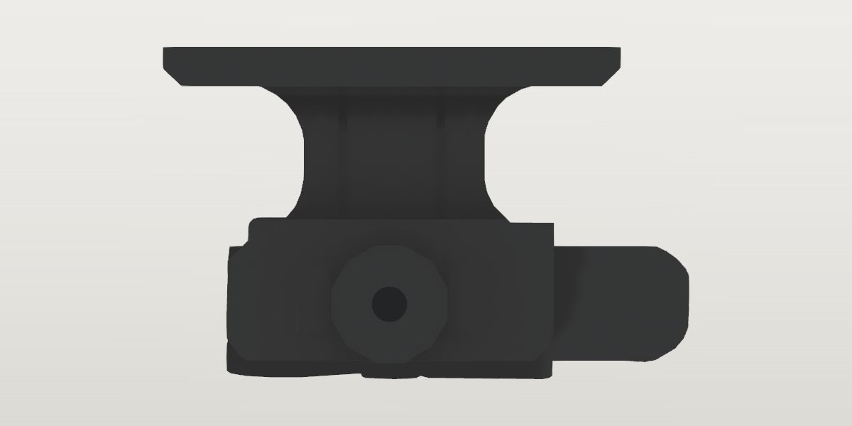
- Weight
- 2.08 oz ± 0.4 oz Conflictworked out: The model's volume: the aluminium 1.2699 cubic inches as the maker's 6061 (std.density.aluminium, 0.098 lb a cubic inch: 1.99 oz) and the steel 0.02 (the lock button, the nut's screw, the shaft in its slot) as steel (std.density.steel: 0.09 oz), from pipeline/blender/midwest_mk2_qd_t2.py's manifest. The ± is a fifth: the widths across it are assumed.Its sources span 1.68 oz to 3.65 oz.
- Lowest price
- $129.95 at Primary Arms, read Nov 21, 2026 (Black), out of stock that day
- Maker's number
- MI-MK2-QDT21/3
- Colour
- Black (placeholder)
- Drawn as
- modelled
- Maker's page
- midwestindustriesinc.com
In “22RB .22 LR rifle”, a build on the start page, in place of its Holosun 1.63 in lower 1/3 co-witness pedestal mount (HS-MOUNT-AR-RISER-ARO).
Its figures
Every figure the site draws and checks it by, with where it came from. Open one for each source's reading, and why one is used where they differ.
The deck's top (where the dot's base sits) above the rail's top1.1 in ± 0.06 in 27.9 mmProvisionalPhoto: MI-MK2-QDT213-ivr, the mount with a T-2 on it, straight right side) and 723bb889a675 (MI-MK2-QDT213-l, the mount alone, straight left side
Photo 1.1 in ± 0.06 in used
MI-MK2-QDT213-ivr, the mount with a T-2 on it, straight right side) and 723bb889a675 (MI-MK2-QDT213-l, the mount alone, straight left side, harvested
Scale: in the dot's photo the T-2 (342.6 px/in: its 68 mm and its windage cap, ledger aimpoint-micro-t-2), its axis at row 416 (the middle of both end rings); in the left view the deck's length as read in the dot's photo (deck_length, 1.985 in, over the deck's 736 px: 370.8 px/in). Read by The dot's base, which the deck's side lips hide, is the T-2's axis less its own axis over its base (aimpoint-micro-t-2.axis_above_base, 0.589 in: row 617.8), 0.049 in under the lips' top (row 601). The rail's top, which no side view shows, is taken at the axis of the clamp's cross shaft: the centre of the 12-sided adjustment nut on it in the left view (row 806, its rings' centre), 1.162 in under the lips' top there (row 375), and 0.018 in under the rail's top as a shaft lying in a rail slot is (its foot on the slot's floor, std.picatinny.slot_depth 0.118, its diameter assumed between 0.15 and 0.25 in: ± 0.03). 1.162 - 0.049 - 0.018. The ± is the T-2's 0.037 over its base, the shaft's 0.03 and the scale's 2%. Checked in the maker's quarter view of the pair from the front right (13199957f5cb): the base's front end face, the far jaw's notch for the rail's head in it, puts the rail's top at row 994 in the side view by the face's own proportions, within 0.02 in of this
The maker gives no height for this mount, only its name, "1/3 Cowitness" (the page's option; its feature line: "Available in Low, Lower 1/3 Cowitness, Absolute Cowitness, and NV 2.26” height"), and Primary Arms the words "This is the lower 1/3 cowitness height, which sets the optic higher so your iron sights appear in the lower third of the optic window." No dot is named for any height. Read here on the maker's photographs: a claim the test holds the reading to (a T-2 on it stands higher than a standard rear sight's 1.41 to 1.42 in), not a figure. A lead, not a source: a forum post the harvester was refused (ar15.com) is quoted by a search result as "Midwest Industries is 1.65 for lower 1/3 height", of no named model; this reading puts a T-2's axis at 1.69.
The deck's two side lips: their top over the deck's top, where the dot's base sits0.049 in ± 0.04 in 1.2 mmProvisionalPhoto: Midwest Industries' MI-MK2-QDT213-ivr: this mount with a Micro T-2 on it, straight right side on white, 1280 x 1280, muzzle to the right. The dot is named on no page; it is an Aimpoint Micro T-2 by its outline and controls, matched against Aimpoint's own right profile of 200198 (a copy on file): the intensity switch with its INTENSITY arrow, the windage cap with its two pins behind it, the elevation turret in its housing, without lens covers
Photo 0.049 in ± 0.04 in used
Midwest Industries' MI-MK2-QDT213-ivr: this mount with a Micro T-2 on it, straight right side on white, 1280 x 1280, muzzle to the right. The dot is named on no page; it is an Aimpoint Micro T-2 by its outline and controls, matched against Aimpoint's own right profile of 200198 (a copy on file): the intensity switch with its INTENSITY arrow, the windage cap with its two pins behind it, the elevation turret in its housing, without lens covers, harvested
Scale: the T-2 in the same photo: its two ends 934 px apart (x 172 to 1106) for the sheet's 68 mm "Sight Only" (aimpoint-micro-t-2.sight_length: 348.9 px/in), and its windage cap 182 px across (row 425, x 345 to 527) for aimpoint-micro-t-2.windage_od, 0.541 in (336.4 px/in): the mean, 342.6 px/in, ± 2%. The two disagree by 3.7%: whether the rings at the dot's ends are the bare sight's own isn't certain. The dot's axis is the middle of each end ring (rows 230 to 600 and 263 to 570: 415 and 416.5, the photo level within a pixel and a half). Read by the deck's top edge in the side view (the lips' top: row 601, where the silhouette steps in from the dot's 283 to 1088 to the deck's 292 to 975) over the T-2's base as its axis puts it (row 617.8): 16.8 px. The ± is the T-2's own over its base
Two lips along the deck's long sides that locate the dot's base between them (every quarter view: 5fbbfa2e9c84, c57e405080b1, ad7a9c06e6ce). Not drawn (the part's approximations): the three dots on file are drawn with bases as wide as their housings, wider than the deck, and the lips would stand in them.
The footprint's middle along the deck, ahead of the clamp's middle-0.01 in ± 0.015 in -0.3 mmProvisionalPhoto: left view) and caa89ca71b96 (right view
Photo -0.01 in ± 0.015 in used
left view) and caa89ca71b96 (right view, harvested
Scale: each view's deck length as deck_length (370.8 and 362.2 px/in). Read by the deck's ends (left view: x 237 and 973, middle 605; right view: 332 and 1051, middle 691.5) against the base's (left: 341 and 862, middle 601.5; right, its foot under the lever: 439 and 951, middle 695): the deck's middle 3.5 px behind the base's in both, 0.009 in
The deck's middle over the clamp base's middle, in both straight side views: the four holes and the lug are about the deck's middle (the cross-bolt MK2's view from below: the holes' middle 3 px off the deck's in 1235).
The deck's length along the rail (the plate the dot sits on)1.985 in ± 0.04 in 50.4 mmCorroboratedPhoto: Midwest Industries' MI-MK2-QDT213-ivr: this mount with a Micro T-2 on it, straight right side on white, 1280 x 1280, muzzle to the right. The dot is named on no page; it is an Aimpoint Micro T-2 by its outline and controls, matched against Aimpoint's own right profile of 200198 (a copy on file): the intensity switch with its INTENSITY arrow, the windage cap with its two pins behind it, the elevation turret in its housing, without lens covers
Photo 1.985 in ± 0.04 in used
Midwest Industries' MI-MK2-QDT213-ivr: this mount with a Micro T-2 on it, straight right side on white, 1280 x 1280, muzzle to the right. The dot is named on no page; it is an Aimpoint Micro T-2 by its outline and controls, matched against Aimpoint's own right profile of 200198 (a copy on file): the intensity switch with its INTENSITY arrow, the windage cap with its two pins behind it, the elevation turret in its housing, without lens covers, harvested
Scale: the T-2 in the same photo: its two ends 934 px apart (x 172 to 1106) for the sheet's 68 mm "Sight Only" (aimpoint-micro-t-2.sight_length: 348.9 px/in), and its windage cap 182 px across (row 425, x 345 to 527) for aimpoint-micro-t-2.windage_od, 0.541 in (336.4 px/in): the mean, 342.6 px/in, ± 2%. The two disagree by 3.7%: whether the rings at the dot's ends are the bare sight's own isn't certain. The dot's axis is the middle of each end ring (rows 230 to 600 and 263 to 570: 415 and 416.5, the photo level within a pixel and a half). Read by the deck plate's two ends under the dot, rows 613 to 658: x 294 to 974, 680 px
Photo 1.946 in ± 0.02 in
MI-MK2T213_bottom: the CROSS-BOLT MK2 T2 mount's 1/3 height, MK2T2AIMPO-2, a product of its own, straight from below, 1280 x 1280: the deck's underside round its clamp, the deck's four holes through it, cast 'T2 1/3', harvested
Scale: the clamp's two hooks seen from below, 475 px apart (y 390 to 865) for the rail's lower gauge line, std.picatinny.bevel_width 0.748 in (635 px/in): where the hooks come in to under the rail. Read by the deck's ends seen from below past the clamp, x 22.5 to 1257.5: 1235 px. The cross-bolt MK2's deck, another product's: whether its deck is this one's is what the agreement says
Read on this mount, scaled by the dot on it; the cross-bolt mount's deck, scaled by its hooks as the rail's lower gauge line, is 2% shorter, inside the two readings' ±: the deck is one plate in both products by this, and the hooks may stand a little wider than the line.
The deck's width across the rifle0.897 in ± 0.03 in 22.8 mmProvisionalPhoto: MI-MK2T213_bottom: the CROSS-BOLT MK2 T2 mount's 1/3 height, MK2T2AIMPO-2, a product of its own, straight from below, 1280 x 1280: the deck's underside round its clamp, the deck's four holes through it, cast 'T2 1/3'
Photo 0.897 in ± 0.03 in used
MI-MK2T213_bottom: the CROSS-BOLT MK2 T2 mount's 1/3 height, MK2T2AIMPO-2, a product of its own, straight from below, 1280 x 1280: the deck's underside round its clamp, the deck's four holes through it, cast 'T2 1/3', harvested
Scale: the deck's own length there (1235 px) as deck_length. Read by the plate's two long sides at column 60, past the clamp: rows 362 and 919, 557 px: 0.452 of its length
No straight view of this mount from above, below or an end is on file (its quarter views only): read on the cross-bolt MK2's view from below, whose deck's length agrees with this one's (deck_length).
The deck's screw holes: their spacing along the rail (two at each end)1.418 in ± 0.02 in 36 mmProvisionalPhoto: MI-MK2T213_bottom: the CROSS-BOLT MK2 T2 mount's 1/3 height, MK2T2AIMPO-2, a product of its own, straight from below, 1280 x 1280: the deck's underside round its clamp, the deck's four holes through it, cast 'T2 1/3'
Photo 1.418 in ± 0.02 in used
MI-MK2T213_bottom: the CROSS-BOLT MK2 T2 mount's 1/3 height, MK2T2AIMPO-2, a product of its own, straight from below, 1280 x 1280: the deck's underside round its clamp, the deck's four holes through it, cast 'T2 1/3', harvested
Scale: the deck's own length there (1235 px) as deck_length. Read by the four holes through the plate either side of the clamp: their middles at x 196 and 1078 (each hole's two edges along row 520 and column 190), 882 px. Four holes, two at each end, in the quarter views of this mount too (c57e405080b1, 165f8d951a1d)
The deck's screw holes: their spacing across the rifle0.4 in ± 0.02 in 10.2 mmProvisionalPhoto: MI-MK2T213_bottom: the CROSS-BOLT MK2 T2 mount's 1/3 height, MK2T2AIMPO-2, a product of its own, straight from below, 1280 x 1280: the deck's underside round its clamp, the deck's four holes through it, cast 'T2 1/3'
Photo 0.4 in ± 0.02 in used
MI-MK2T213_bottom: the CROSS-BOLT MK2 T2 mount's 1/3 height, MK2T2AIMPO-2, a product of its own, straight from below, 1280 x 1280: the deck's underside round its clamp, the deck's four holes through it, cast 'T2 1/3', harvested
Scale: the deck's own length there (1235 px) as deck_length. Read by the holes' middles at rows 517 and 766 (column 190), 249 px
The deck's screw holes: their diameter0.129 in ± 0.015 in 3.3 mmProvisionalPhoto: MI-MK2T213_bottom: the CROSS-BOLT MK2 T2 mount's 1/3 height, MK2T2AIMPO-2, a product of its own, straight from below, 1280 x 1280: the deck's underside round its clamp, the deck's four holes through it, cast 'T2 1/3'
Photo 0.129 in ± 0.015 in used
MI-MK2T213_bottom: the CROSS-BOLT MK2 T2 mount's 1/3 height, MK2T2AIMPO-2, a product of its own, straight from below, 1280 x 1280: the deck's underside round its clamp, the deck's four holes through it, cast 'T2 1/3', harvested
Scale: the deck's own length there (1235 px) as deck_length. Read by each hole's edges: 80 px across (rows 477 to 557.5 and 725 to 806.5; columns 1038.5 to 1118)
Clamp length along the rail (at its foot)1.405 in ± 0.025 in 35.7 mmCorroboratedPhoto: MI-MK2-QDT213-l: the mount alone, straight left side on white, 1280 x 1280, muzzle to the left: the adjustment nut in its pocket, the lever's tail behind
Photo 1.405 in ± 0.025 in used
MI-MK2-QDT213-l: the mount alone, straight left side on white, 1280 x 1280, muzzle to the left: the adjustment nut in its pocket, the lever's tail behind, harvested
Scale: the deck's length as deck_length, 736 px (370.8 px/in). Read by the base block's two end faces, rows 747 to 835: x 341 to 862, 521 px
Photo 1.414 in ± 0.025 in
MI-MK2-QDT213-r: the mount alone, straight right side on white, 1280 x 1280, muzzle to the right, the lever closed along the base, harvested
Scale: the deck's length as deck_length, 719 px (362.2 px/in). Read by the base's foot under the lever, rows 890 to 900: x 439 to 951, 512 px
The base block itself, end to end, on the side with nothing in front of it; the right side's foot is the lever side's jaw, 0.01 in longer, within both readings.
The clamp base, from its rear face to its front face: the lever's tail reaches 0.5 in further back beside it (the right view) and isn't counted.
The base's foot below the rail's top (the nut's side)0.277 in ± 0.04 in 7 mmProvisionalPhoto: MI-MK2-QDT213-l: the mount alone, straight left side on white, 1280 x 1280, muzzle to the left: the adjustment nut in its pocket, the lever's tail behind
Photo 0.277 in ± 0.04 in used
MI-MK2-QDT213-l: the mount alone, straight left side on white, 1280 x 1280, muzzle to the left: the adjustment nut in its pocket, the lever's tail behind, harvested
Scale: the deck's length as deck_length (370.8 px/in). Read by the base's foot (row 902) under the cross shaft's axis (the nut's centre, row 806): 96 px, and the rail's top 0.018 in over the axis (deck_above_rail's method)
The base block's top over the rail's top, where the web stands on it0.35 in ± 0.03 in 8.9 mmProvisionalPhoto: MI-MK2-QDT213-l: the mount alone, straight left side on white, 1280 x 1280, muzzle to the left: the adjustment nut in its pocket, the lever's tail behind
Photo 0.35 in ± 0.03 in used
MI-MK2-QDT213-l: the mount alone, straight left side on white, 1280 x 1280, muzzle to the left: the adjustment nut in its pocket, the lever's tail behind, harvested
Scale: the deck's length as deck_length (370.8 px/in). Read by the base's top face either side of the web's flare (rows 676 behind it and 668 ahead of it: 0.33 and 0.35 over the rail's top as deck_above_rail places it, row 799.3; the traced outline has 0.337 and 0.359)
The deck plate's lower face under the deck's top (where the dot's base sits)0.173 in ± 0.02 in 4.4 mmProvisionalPhoto: left view) and caa89ca71b96 (right view
Photo 0.173 in ± 0.02 in used
left view) and caa89ca71b96 (right view, harvested
Scale: each view's deck length as deck_length (370.8 and 362.2 px/in). Read by the deck plate's lower flats at its ends (row 455 in both) under the lips' top (rows 376 and 371), less the lips' height (deck_lip_height): 0.164 and 0.183. The dot's photo, taken from above the mount, reads it deeper (0.199) and isn't used
The two grooves down each flank of the web, either side of its oval panel: their spacing along the rail0.426 in ± 0.02 in 10.8 mmProvisionalPhoto: MI-MK2-QDT213-l: the mount alone, straight left side on white, 1280 x 1280, muzzle to the left: the adjustment nut in its pocket, the lever's tail behind
Photo 0.426 in ± 0.02 in used
MI-MK2-QDT213-l: the mount alone, straight left side on white, 1280 x 1280, muzzle to the left: the adjustment nut in its pocket, the lever's tail behind, harvested
Scale: the deck's length as deck_length (370.8 px/in). Read by the grooves' middles at x 532 and 690 (rows 500 to 650), 158 px, about the web's middle (608.5) within 2.5 px
The web's flank grooves: their width0.038 in ± 0.01 in 1 mmProvisionalPhoto: MI-MK2-QDT213-l: the mount alone, straight left side on white, 1280 x 1280, muzzle to the left: the adjustment nut in its pocket, the lever's tail behind
Photo 0.038 in ± 0.01 in used
MI-MK2-QDT213-l: the mount alone, straight left side on white, 1280 x 1280, muzzle to the left: the adjustment nut in its pocket, the lever's tail behind, harvested
Scale: the deck's length as deck_length (370.8 px/in). Read by each dark band 14 px across (525 to 539, 683 to 697)
The 12-sided adjustment nut, across its flats0.504 in ± 0.02 in 12.8 mmProvisionalPhoto: MI-MK2-QDT213-l: the mount alone, straight left side on white, 1280 x 1280, muzzle to the left: the adjustment nut in its pocket, the lever's tail behind
Photo 0.504 in ± 0.02 in used
MI-MK2-QDT213-l: the mount alone, straight left side on white, 1280 x 1280, muzzle to the left: the adjustment nut in its pocket, the lever's tail behind, harvested
Scale: the deck's length as deck_length (370.8 px/in). Read by its top flat (row 713) to its bottom flat (row 900) about its centre (row 806): 187 px
The maker's sheet: "Rotate the 12 sided adjustment nut one notch at a time to get the exact tension you want." Its twelve sides, counted on the left view: a flat at top and bottom and five corners between.
The base block's sides out from the rail's middle0.49 in ± 0.04 in 12.4 mmProvisionalWorked out: An assumption for the drawing, not a reading: no straight view of this mount from an end, above or below is on file. In the maker's quarter view from the front right (13199957f5cb) the base's left face stands a little outside the deck's left edge (deck_width), and its jaws must hold the rail's head (0.835 in) with walls round it.
Worked out 0.49 in ± 0.04 in used
An assumption for the drawing, not a reading: no straight view of this mount from an end, above or below is on file. In the maker's quarter view from the front right (13199957f5cb) the base's left face stands a little outside the deck's left edge (deck_width), and its jaws must hold the rail's head (0.835 in) with walls round it., harvested
The web between the deck and the base, across the rifle0.5 in ± 0.1 in 12.7 mmProvisionalWorked out: An assumption for the drawing, not a reading: the web is seen across only in the quarter views (5fbbfa2e9c84, ad7a9c06e6ce), where it is about half the deck's width; no straight view of it from an end is on file.
Worked out 0.5 in ± 0.1 in used
An assumption for the drawing, not a reading: the web is seen across only in the quarter views (5fbbfa2e9c84, ad7a9c06e6ce), where it is about half the deck's width; no straight view of it from an end is on file., harvested
The web's flank grooves: how far they are cut in0.03 in ± 0.015 in 0.8 mmProvisionalWorked out: An assumption for the drawing, not a reading: the oval panel with the maker's mark on the right flank and the plain one on the left stand between two grooves in both side views, and no view shows them in profile.
Worked out 0.03 in ± 0.015 in used
An assumption for the drawing, not a reading: the oval panel with the maker's mark on the right flank and the plain one on the left stand between two grooves in both side views, and no view shows them in profile., harvested
The QD lever and its jaw plate: how far they stand out from the base's right side0.17 in ± 0.05 in 4.3 mmProvisionalWorked out: An assumption for the drawing, not a reading: the lever lies along the base's right side in every view, and its thickness is seen only in the quarter views (5fbbfa2e9c84, c57e405080b1), where it stands out about a third of the base's height; no view from an end is on file.
Worked out 0.17 in ± 0.05 in used
An assumption for the drawing, not a reading: the lever lies along the base's right side in every view, and its thickness is seen only in the quarter views (5fbbfa2e9c84, c57e405080b1), where it stands out about a third of the base's height; no view from an end is on file., harvested
The adjustment nut: how far it stands out of its pocket in the base's left side0.1 in ± 0.04 in 2.5 mmProvisionalWorked out: An assumption for the drawing, not a reading: the nut is seen face on (the left view) and in the quarter views from the left (c57e405080b1), where its face stands a little out of the base's side; no view from an end is on file.
Worked out 0.1 in ± 0.04 in used
An assumption for the drawing, not a reading: the nut is seen face on (the left view) and in the quarter views from the left (c57e405080b1), where its face stands a little out of the base's side; no view from an end is on file., harvested
The window in the lever round its lock button: its rear end-0.35 in ± 0.01 in -8.9 mmProvisionalPhoto: MI-MK2-QDT213-r: the mount alone, straight right side on white, 1280 x 1280, muzzle to the right, the lever closed along the base
Photo -0.35 in ± 0.01 in used
MI-MK2-QDT213-r: the mount alone, straight right side on white, 1280 x 1280, muzzle to the right, the lever closed along the base, harvested
Scale: the deck's ends at x 332 and 1051 as deck_x and deck_length (362.2 px/in). Read by the dark opening's rear end at x 568
The window in the lever: its front end (round)0.297 in ± 0.01 in 7.5 mmProvisionalPhoto: MI-MK2-QDT213-r: the mount alone, straight right side on white, 1280 x 1280, muzzle to the right, the lever closed along the base
Photo 0.297 in ± 0.01 in used
MI-MK2-QDT213-r: the mount alone, straight right side on white, 1280 x 1280, muzzle to the right, the lever closed along the base, harvested
Scale: as lever_window_rear_x. Read by the opening's rounded front end at x 803
The window in the lever: its top over the rail's top0.089 in ± 0.01 in 2.3 mmProvisionalPhoto: MI-MK2-QDT213-r: the mount alone, straight right side on white, 1280 x 1280, muzzle to the right, the lever closed along the base
Photo 0.089 in ± 0.01 in used
MI-MK2-QDT213-r: the mount alone, straight right side on white, 1280 x 1280, muzzle to the right, the lever closed along the base, harvested
Scale: as lever_window_rear_x, and the lips' top (row 371) at deck_above_rail + deck_lip_height. Read by the opening's top edge at row 755
The window in the lever: its bottom against the rail's top-0.14 in ± 0.01 in -3.6 mmProvisionalPhoto: MI-MK2-QDT213-r: the mount alone, straight right side on white, 1280 x 1280, muzzle to the right, the lever closed along the base
Photo -0.14 in ± 0.01 in used
MI-MK2-QDT213-r: the mount alone, straight right side on white, 1280 x 1280, muzzle to the right, the lever closed along the base, harvested
Scale: as lever_window_top. Read by the opening's lower edge at row 838
The three flutes across the QD lever's tail: the rearmost's middle-1.182 in ± 0.01 in -30 mmProvisionalPhoto: MI-MK2-QDT213-r: the mount alone, straight right side on white, 1280 x 1280, muzzle to the right, the lever closed along the base
Photo -1.182 in ± 0.01 in used
MI-MK2-QDT213-r: the mount alone, straight right side on white, 1280 x 1280, muzzle to the right, the lever closed along the base, harvested
Scale: as lever_window_rear_x. Read by the dark bands across the lever's tail along row 790 (4 rows each way), their middles at x 267, 335 and 402: three, counted on the straight view of the whole tail
The lever's tail flutes: their spacing0.187 in ± 0.01 in 4.7 mmProvisionalPhoto: MI-MK2-QDT213-r: the mount alone, straight right side on white, 1280 x 1280, muzzle to the right, the lever closed along the base
Photo 0.187 in ± 0.01 in used
MI-MK2-QDT213-r: the mount alone, straight right side on white, 1280 x 1280, muzzle to the right, the lever closed along the base, harvested
Scale: as lever_window_rear_x. Read by x 267 to 402 over two spacings: 67.5 px
The lever's tail flutes: their width0.04 in ± 0.01 in 1 mmProvisionalPhoto: MI-MK2-QDT213-r: the mount alone, straight right side on white, 1280 x 1280, muzzle to the right, the lever closed along the base
Photo 0.04 in ± 0.01 in used
MI-MK2-QDT213-r: the mount alone, straight right side on white, 1280 x 1280, muzzle to the right, the lever closed along the base, harvested
Scale: as lever_window_rear_x. Read by each dark band about 14 px across at half its depth of tone
The grooves down the jaw plate at the lever's front: the rearmost's middle0.505 in ± 0.01 in 12.8 mmProvisionalPhoto: MI-MK2-QDT213-r: the mount alone, straight right side on white, 1280 x 1280, muzzle to the right, the lever closed along the base
Photo 0.505 in ± 0.01 in used
MI-MK2-QDT213-r: the mount alone, straight right side on white, 1280 x 1280, muzzle to the right, the lever closed along the base, harvested
Scale: as lever_window_rear_x. Read by the dark lines down the jaw plate along row 790, at x 878, 905 and 933: three, between four ribs
The jaw plate's grooves: their spacing0.076 in ± 0.005 in 1.9 mmProvisionalPhoto: MI-MK2-QDT213-r: the mount alone, straight right side on white, 1280 x 1280, muzzle to the right, the lever closed along the base
Photo 0.076 in ± 0.005 in used
MI-MK2-QDT213-r: the mount alone, straight right side on white, 1280 x 1280, muzzle to the right, the lever closed along the base, harvested
Scale: as lever_window_rear_x. Read by x 878 to 933 over two spacings: 27.5 px
The jaw plate's grooves: their width0.022 in ± 0.006 in 0.6 mmProvisionalPhoto: MI-MK2-QDT213-r: the mount alone, straight right side on white, 1280 x 1280, muzzle to the right, the lever closed along the base
Photo 0.022 in ± 0.006 in used
MI-MK2-QDT213-r: the mount alone, straight right side on white, 1280 x 1280, muzzle to the right, the lever closed along the base, harvested
Scale: as lever_window_rear_x. Read by each dark line about 8 px across
The lever's flutes and the jaw plate's grooves: how deep they are cut0.02 in ± 0.01 in 0.5 mmProvisionalWorked out: An assumption for the drawing, not a reading: both are seen face on in the right view and from the front right in the quarter views, never in profile.
Worked out 0.02 in ± 0.01 in used
An assumption for the drawing, not a reading: both are seen face on in the right view and from the front right in the quarter views, never in profile., harvested
The lock button in the lever's window: its rear end-0.241 in ± 0.01 in -6.1 mmProvisionalPhoto: MI-MK2-QDT213-r: the mount alone, straight right side on white, 1280 x 1280, muzzle to the right, the lever closed along the base
Photo -0.241 in ± 0.01 in used
MI-MK2-QDT213-r: the mount alone, straight right side on white, 1280 x 1280, muzzle to the right, the lever closed along the base, harvested
Scale: as lever_window_rear_x. Read by the lighter block's rear end at x 608
The lock button: its front end0.16 in ± 0.01 in 4.1 mmProvisionalPhoto: MI-MK2-QDT213-r: the mount alone, straight right side on white, 1280 x 1280, muzzle to the right, the lever closed along the base
Photo 0.16 in ± 0.01 in used
MI-MK2-QDT213-r: the mount alone, straight right side on white, 1280 x 1280, muzzle to the right, the lever closed along the base, harvested
Scale: as lever_window_rear_x. Read by the block's front end at x 753
The lock button: its top over the rail's top0.068 in ± 0.01 in 1.7 mmProvisionalPhoto: MI-MK2-QDT213-r: the mount alone, straight right side on white, 1280 x 1280, muzzle to the right, the lever closed along the base
Photo 0.068 in ± 0.01 in used
MI-MK2-QDT213-r: the mount alone, straight right side on white, 1280 x 1280, muzzle to the right, the lever closed along the base, harvested
Scale: as lever_window_top. Read by the block's top edge at row 762.7
The lock button: its bottom against the rail's top-0.114 in ± 0.01 in -2.9 mmProvisionalPhoto: MI-MK2-QDT213-r: the mount alone, straight right side on white, 1280 x 1280, muzzle to the right, the lever closed along the base
Photo -0.114 in ± 0.01 in used
MI-MK2-QDT213-r: the mount alone, straight right side on white, 1280 x 1280, muzzle to the right, the lever closed along the base, harvested
Scale: as lever_window_top. Read by the block's lower edge at row 828.6
The two ribs either side of the adjustment nut on the base's left side: their inner faces, out from the nut's axis0.26 in ± 0.015 in 6.6 mmProvisionalPhoto: MI-MK2-QDT213-l: the mount alone, straight left side on white, 1280 x 1280, muzzle to the left: the adjustment nut in its pocket, the lever's tail behind
Photo 0.26 in ± 0.015 in used
MI-MK2-QDT213-l: the mount alone, straight left side on white, 1280 x 1280, muzzle to the left: the adjustment nut in its pocket, the lever's tail behind, harvested
Scale: the traced outline's placement (profiles.side: 370.3 px/in, the deck's ends at deck_length about deck_x). Read by the ribs' inner edges at x 501 and 694 (row 800) about the nut's centre (601): 0.271 and 0.250
The ribs either side of the nut: their outer faces, out from the nut's axis0.4 in ± 0.015 in 10.2 mmProvisionalPhoto: MI-MK2-QDT213-l: the mount alone, straight left side on white, 1280 x 1280, muzzle to the left: the adjustment nut in its pocket, the lever's tail behind
Photo 0.4 in ± 0.015 in used
MI-MK2-QDT213-l: the mount alone, straight left side on white, 1280 x 1280, muzzle to the left: the adjustment nut in its pocket, the lever's tail behind, harvested
Scale: as nut_rib_inner_x. Read by the ribs' outer edges at x 452 and 747: 0.403 and 0.393
The ribs either side of the nut: their top over the rail's top0.15 in ± 0.015 in 3.8 mmProvisionalPhoto: MI-MK2-QDT213-l: the mount alone, straight left side on white, 1280 x 1280, muzzle to the left: the adjustment nut in its pocket, the lever's tail behind
Photo 0.15 in ± 0.015 in used
MI-MK2-QDT213-l: the mount alone, straight left side on white, 1280 x 1280, muzzle to the left: the adjustment nut in its pocket, the lever's tail behind, harvested
Scale: as nut_rib_inner_x. Read by their top edges at row 746 (column 476)
The ribs either side of the nut: their bottom against the rail's top-0.134 in ± 0.015 in -3.4 mmProvisionalPhoto: MI-MK2-QDT213-l: the mount alone, straight left side on white, 1280 x 1280, muzzle to the left: the adjustment nut in its pocket, the lever's tail behind
Photo -0.134 in ± 0.015 in used
MI-MK2-QDT213-l: the mount alone, straight left side on white, 1280 x 1280, muzzle to the left: the adjustment nut in its pocket, the lever's tail behind, harvested
Scale: as nut_rib_inner_x. Read by their lower edges at row 851 (column 476)
The ribs either side of the nut: how far they stand out of the base's side0.03 in ± 0.015 in 0.8 mmProvisionalWorked out: An assumption for the drawing, not a reading: they are seen face on in the left view, lit along their top and bottom edges, and from the rear left in c57e405080b1, where they stand a little out of the side; no view shows them in profile.
Worked out 0.03 in ± 0.015 in used
An assumption for the drawing, not a reading: they are seen face on in the left view, lit along their top and bottom edges, and from the rear left in c57e405080b1, where they stand a little out of the side; no view shows them in profile., harvested
The slotted screw in the adjustment nut's middle: its head's diameter0.154 in ± 0.01 in 3.9 mmProvisionalPhoto: MI-MK2-QDT213-l: the mount alone, straight left side on white, 1280 x 1280, muzzle to the left: the adjustment nut in its pocket, the lever's tail behind
Photo 0.154 in ± 0.01 in used
MI-MK2-QDT213-l: the mount alone, straight left side on white, 1280 x 1280, muzzle to the left: the adjustment nut in its pocket, the lever's tail behind, harvested
Scale: the deck's length as deck_length (370.8 px/in). Read by its head's rim across row 806: x 579.5 to 636.5, 57 px
The cross shaft the lever and the nut are on: its diameter, where it crosses the rail in a slot0.2 in ± 0.05 in 5.1 mmProvisionalWorked out: An assumption for the drawing, not a reading: the shaft is hidden in the base in every view (its end is the screw in the nut's middle). Taken between 0.15 and 0.25 in, which is what deck_above_rail's ± allows for where it lies in its slot.
Worked out 0.2 in ± 0.05 in used
An assumption for the drawing, not a reading: the shaft is hidden in the base in every view (its end is the screw in the nut's middle). Taken between 0.15 and 0.25 in, which is what deck_above_rail's ± allows for where it lies in its slot., harvested
The break on the aluminium's edges0.012 in ± 0.006 in 0.3 mmProvisionalWorked out: An assumption for the drawing, not a reading: the edges read slightly round in the maker's photographs, by how much isn't read.
Worked out 0.012 in ± 0.006 in used
An assumption for the drawing, not a reading: the edges read slightly round in the maker's photographs, by how much isn't read., harvested
What it goes with
By the way it mounts, and the figures each part on file states: a part whose figures say it doesn't fit is left out, and one whose fit can't be checked from what is published is marked. A check is against published figures, not a guarantee.
Picatinny rail (MIL-STD-1913)
- Uppers
- Aero Precision M4E1 Enhanced Upper Receiver Stripped, Aero Precision M4E1 Threaded upper receiver, BCM M4 Upper Receiver Assembly (w/ Laser T-Markings), Expo Arms 7075 Stripped AR-15 Upper Receiver, Geissele Automatics Super Duty Stripped Upper Receiver, Nordic Components 22RB .22 LR upper, 16", Palmetto State Armory AR-15 Stripped Upper Receiver, Panzer Arms AR57 ULT Complete AR-15 Upper Receiver - 5.7x28mm - 12", Panzer Arms AR57 Ultra Light Tactical Complete AR-15 Upper Receiver - 5.7x28mm - 16"
- Handguards
- Aero Precision AR15 10.3" R-ONE M-LOK handguard, Aero Precision AR15 12.7" R-ONE M-LOK handguard, Aero Precision AR15 15" Enhanced M-LOK Handguard, Gen 2, Aero Precision AR15 15" R-ONE M-LOK handguard, Aero Precision AR15 15" S-ONE M-LOK Handguard, Aero Precision AR15 16.6" R-ONE M-LOK handguard, Aero Precision AR15 7.3" R-ONE M-LOK handguard, Aero Precision AR15 9.3" R-ONE M-LOK handguard, BCM MCMR-10 (M-LOK® Compatible* Modular Rail), BCM MCMR-13 (M-LOK® Compatible* Modular Rail), BCM MCMR-15 (M-LOK® Compatible* Modular Rail), Expo Arms Free Float AR-15 Handguard - M-LOK - 15", Geissele Automatics 10.5" Super Modular Rail MK16 M-LOK, Geissele Automatics 13.5" Super Modular Rail MK16 M-LOK, Geissele Automatics 15" Super Modular Rail MK16 M-LOK, MAS Defense 12.62" NERO M-LOK FREE FLOAT, MAS Defense 15" NERO M-LOK FREE FLOAT, MAS Defense 9.87" NERO M-LOK FREE FLOAT, Midwest Industries AR-15/M16 Two Piece Drop-In Handguard, M-LOK® (Carbine), Midwest Industries AR-15/M16 Two Piece Drop-In Handguard, M-LOK® (Mid-Length), Midwest Industries Combat Rail One Piece Free Float Handguard, M-LOK™ (15")
- Frames
- Taurus TX22 Gen 2 frame
- Rail sections
- Magpul M-LOK® Aluminum Rail, 3 Slots, Magpul M-LOK® Aluminum Rail, 5 Slots, Magpul M-LOK® Aluminum Rail, 7 Slots, Magpul M-LOK® Aluminum Rail, 9 Slots, Magpul M-LOK® Polymer Rail, 11 Slots, Magpul M-LOK® Polymer Rail, 3 Slots, Magpul M-LOK® Polymer Rail, 5 Slots, Magpul M-LOK® Polymer Rail, 7 Slots, Magpul M-LOK® Polymer Rail, 9 Slots
Prices on file
Each seller's latest reading of its own page: before tax and shipping, and not a quote. The pages are read again every night.
- Primary Arms $129.95 Black Nov 21, 2026, out of stock that day