Lower receiver
Bear Creek Arsenal BC-15 Multi Caliber, Lower Receiver, Black Anodized
Bear Creek's forged stripped lower, roll-marked BCA15 and MULTI CALIBER: "fully machined, anodized black and forged to mil-spec from 7075 aluminum" (Bear Creek). Primary Arms lists it as "Bear Creek Arsenal AR-15 Lower Receiver - Stripped Lower" (BCA-LR-15) and says it "ships stripped, ready for the lower parts kit, buffer assembly, and stock of the builder's choice". No trigger guard: a separate one pins into its ears.
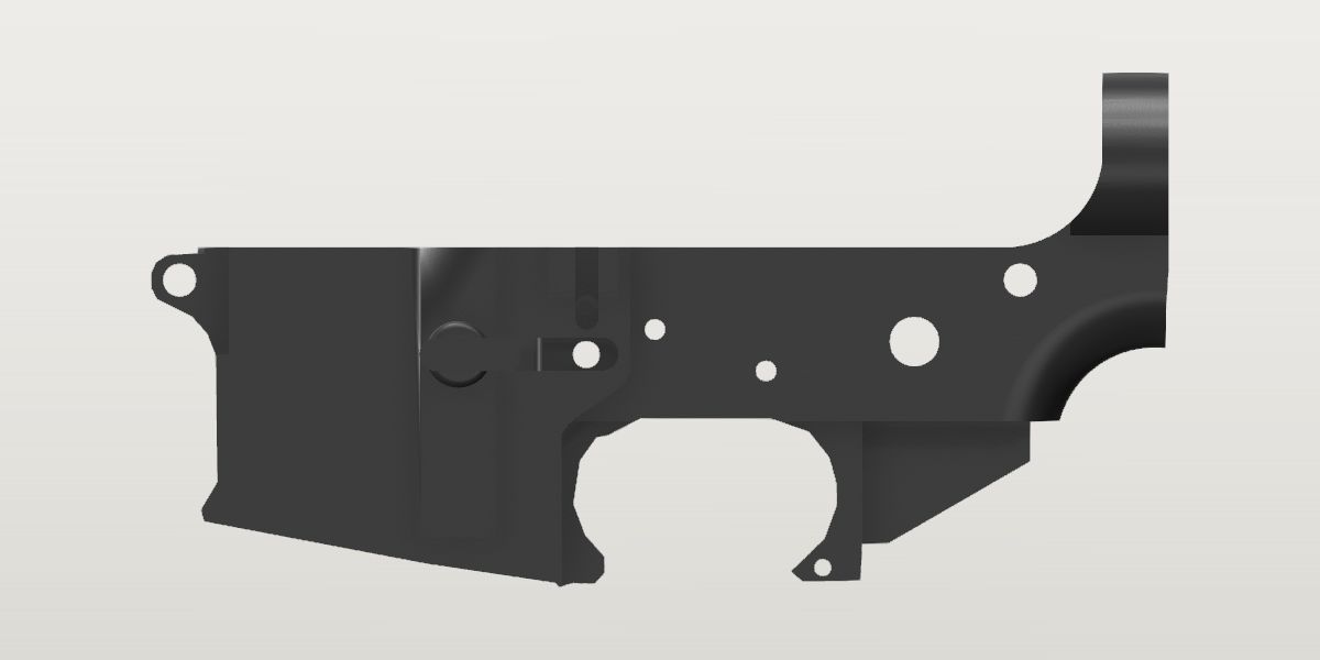
- Weight
- 11.2 oz ± 0.05 oz Conflictpublished: AR15Discounts, BCA BC-15 AR-15 Forged Stripped Lower Receiver - LR-15 (SKU 34198), Additional information, a seller, read Oct 5, 2026Its sources span 11.15 oz to 16 oz.
- Lowest price
- $49.95 at AR15Discounts, read Nov 21, 2026 (Black Anodized)
- Maker's number
- LR-15
- Colours
- Black Anodized, Flat Dark Earth
- Drawn as
- modelled
- Maker's page
- bearcreekarsenal.com
In “Budget 16 in carbine”, a build on the start page, as it is.
Its figures
Every figure the site draws and checks it by, with where it came from. Open one for each source's reading, and why one is used where they differ.
Receiver maximum width (Z)0.88 in ± 0.008 in 22.4 mmConfirmedWorked out: {std.ar15.lower_body_width}
Worked out 0.88 in ± 0.008 in used
{std.ar15.lower_body_width}, harvested
Bear Creek: 'Forged to Milspec from 7075 Aluminum'; Primary Arms: 'Fully machined to mil-spec dimensions'. The body's width is the Army drawing's (8448608, Section C-C). Both photos are consistent with it, through cameras whose distance the tower ring's rims set: the far wall's top edge stands 8.8 and 9.2 px over the near wall's where 0.88 gives 9.0 and 9.3, and the far rims seen through the hammer's and trigger's holes sit within a pixel of where 0.88 puts them. Both were part of each camera's fit: consistency, not a reading of the width.
No page states a width and no photo looks along the receiver. The body's is the drawing's; the well's walls (std.ar15.magwell_outside_width) and the tower's ring (std.ar15.buffer_tower_od) stand wider and are drawn at the drawing's too.
Receiver extension (bore) axis above the takedown pin centre0.877 in ± 0.0015 in 22.3 mmConfirmedWorked out: {std.ar15.bore_axis_y}
Worked out 0.8775 in ± 0.0015 in used
{std.ar15.bore_axis_y}, harvested
A mil-spec lower: the threaded hole's centre is the drawing's (.629 above the deck). On both photos the drawing's ring (this axis, std.ar15.buffer_tower_od, its faces) lies on the tower's rims within a pixel (0.011 in) through the cameras the holes fix.
Magazine seat, X (a seated magazine's frame origin ahead of the takedown pin)3.491 in ± 0.03 in 88.7 mmProvisionalWorked out: {bad-workhorse-lower.magazine_seat_x}
Worked out 3.4915 in ± 0.03 in used
{bad-workhorse-lower.magazine_seat_x}, from the site owner
Where a magazine seats in a mil-spec well: from the Army drawing's well and catch slot and the user's own magazine, recorded on the Workhorse. This lower's well is mil-spec by its maker's and sellers' sentences, and its left photo has the catch's slot where the drawing puts it (X 3.05 to 4.54, Y -0.69 to -0.45 on the wall's plane). No photo of a magazine seated in it is on file.
Magazine seat, Y (the feed-lip top of a seated magazine)1.003 in ± 0.05 in 25.5 mmProvisionalWorked out: {bad-workhorse-lower.magazine_seat_y}
Worked out 1.003 in ± 0.05 in used
{bad-workhorse-lower.magazine_seat_y}, from the site owner
As magazine_seat_x: the standard well's and the catch's, not this receiver's outside.
Receiver underside behind the step (where a grip's flat top bears), Y-1.045 in ± 0.03 in -26.5 mmProvisionalPhoto: right side: Primary Arms' photo 269cebb44010 laid square onto the right face by the drawing's holes, the far wall's overhang taken off
Photo -1.045 in ± 0.03 in used
right side: Primary Arms' photo 269cebb44010 laid square onto the right face by the drawing's holes, the far wall's overhang taken off, harvested
Scale: frame from the reviewed holes takedown, pivot (200.0 px/in, rms 0.000 in over 2 points). Read by y_min in x [-0.2, -0.05] of the traced outline (tools/trace.py)
The outline's flat just behind the lug's step: the right face's reading of where a grip's flat top bears (the seat itself is the drawing's: grip_seat_y).
The outline's flat behind the step, read on the right face's plane. Not the seat itself since 2026-10-05 (grip_seat_y takes the drawing's): on a forging the underside behind the lug is round across and the seat's flat stands in from the face, so this edge reads high by its depth x 0.16. The left photo's outline has it at -1.04, and the two agree within 0.015 on every lower edge (the trigger opening -1.06 and -1.065, the ears' bottoms -2.285 and -2.29, -2.33 and -2.345): but both are taken from the same height, so what they share isn't checked by it. The ± allows an edge 0.2 in behind the face.
Grip seat, Y (the underside a grip's flat top bears on, at the takedown pin's X)-1.069 in ± 0.011 in -27.2 mmConfirmedWorked out: {std.ar15.deck_y} - {std.ar15.grip_seat_below_deck}
Worked out -1.0695 in ± 0.0115 in used
{std.ar15.deck_y} - {std.ar15.grip_seat_below_deck}, harvested
A mil-spec lower: the flat the lug hangs from is the drawing's, 1.318 ±.010 below the deck.
Worked out -1.045 in ± 0.03 in
{.grip_mating_y}, harvested
The right photo's outline behind the lug. On a forging the seat's flat reaches the body's side only 0.145 ahead of the pin (its rear edge is a U): what the outline has behind the lug is the flat's edge, 0.04 to 0.16 in from the face, which from this camera reads 0.007 to 0.026 high.
The drawing dimensions it, and the photo agrees within its ±: 0.025 high, of which the flat's edge standing in from the face accounts for 0.007 to 0.026. Everything else read below the pin line on this photo is 0.02 to 0.03 high the same way (the lug's flat, the guard's holes).
The drawing's since 2026-10-05, when the standard's grip mount went into the ledger (std.ar15.grip_seat_below_deck): the photo's own reading (grip_mating_y) is 0.025 above it and inside its ±, and with it the trigger's opening (trigger_opening_top_y, -1.06) would lie below the seat. The lug hung from it is the drawing's too (grip_lug_face_from_pin).
The grip lug's sloped face (the face the grip screw goes into), from the takedown pin's centre, square to the face1.228 in ± 0.01 in 31.2 mmConfirmedWorked out: {std.ar15.grip_lug_face_from_pin}
Worked out 1.228 in ± 0.01 in used
{std.ar15.grip_lug_face_from_pin}, harvested
A mil-spec lower: the lug is the drawing's (1.228 ±.010).
Photo 1.225 in ± 0.02 in
right side, Primary Arms' photo; from about 28 in, 3.5 in above the pin line, harvested
Scale: a pinhole camera fitted to the drawing's hole positions on the part (std.ar15.*: takedown, pivot, selector, hammer, trigger: each rim within 0.007 in), the far rims through the hammer's and trigger's holes, the deck's two edges and the tower ring's rims: 89.3 px/in at the takedown pin, its foot 2.90 ahead of the pin and 3.53 above it, 27.7 in from the right face. Read by the traced outline's sloped stretch under the grip's seat ((0.012, -1.355) to (1.027, -1.930) on the face's plane), each end carried along its line of sight to the lug's own side (0.2525 behind the face: std.ar15.lower_body_width and std.ar15.grip_lug_width), then the line's distance from the pin; ± is 1.5 px and the camera's distance
The drawing's; the photo has it 0.003 nearer the pin once the edge is put at the lug's own depth.
The check that this lower's lug is the drawing's. On the right face's plane the outline's sloped face is 1.173 from the pin: 0.055 nearer than the drawing's. The lug is .375 across (std.ar15.grip_lug_width), so its side stands 0.2525 behind that face, and carried there along the camera's lines of sight the same edge is 1.225 from the pin: the miss is what the lug's depth gives, in size and in sign.
The grip lug's sloped face, from the vertical60° ± 2°ConfirmedWorked out: {std.ar15.grip_lug_face_angle}
Worked out 60 deg ± 2 deg used
{std.ar15.grip_lug_face_angle}, harvested
A mil-spec lower: the lug is the drawing's (60° ±2°).
Photo 60.5 deg ± 1 deg
right side, Primary Arms' photo; from about 28 in, 3.5 in above the pin line, harvested
Scale: a pinhole camera fitted to the drawing's hole positions on the part (std.ar15.*: takedown, pivot, selector, hammer, trigger: each rim within 0.007 in), the far rims through the hammer's and trigger's holes, the deck's two edges and the tower ring's rims: 89.3 px/in at the takedown pin, its foot 2.90 ahead of the pin and 3.53 above it, 27.7 in from the right face. Read by the same stretch of the traced outline, carried to the lug's own side: its lean from the vertical over 1.02 in; ± is 1.5 px at each end
The drawing's; the photo's is half a degree from it.
The grip lug's rear face (under the takedown pin), X-0.075 in ± 0.025 in -1.9 mmConfirmedWorked out: {std.ar15.receiver_rear_x} + {std.ar15.grip_lug_front_from_rear_face} - {std.ar15.grip_lug_length}
Worked out -0.075 in ± 0.025 in used
{std.ar15.receiver_rear_x} + {std.ar15.grip_lug_front_from_rear_face} - {std.ar15.grip_lug_length}, harvested
A mil-spec lower: the lug ends 2.300 ahead of the rear face and is 1.25 long.
Photo -0.054 in ± 0.03 in
right side, Primary Arms' photo; from about 28 in, 3.5 in above the pin line, harvested
Scale: a pinhole camera fitted to the drawing's hole positions on the part (std.ar15.*: takedown, pivot, selector, hammer, trigger: each rim within 0.007 in), the far rims through the hammer's and trigger's holes, the deck's two edges and the tower ring's rims: 89.3 px/in at the takedown pin, its foot 2.90 ahead of the pin and 3.53 above it, 27.7 in from the right face. Read by the traced outline's step down from the seat ((-0.030, -1.047) to (-0.025, -1.317) on the face's plane: grip_shelf_top_x), carried along its lines of sight to the lug's own side; ± is 1.5 px, the camera's distance and where its principal point is
The drawing's; the photo has the face 0.02 ahead of it, inside its ±.
The grip lug's bottom flat (where its sloped face ends, behind the trigger guard's ears), Y-2 in ± 0.021 in -50.8 mmConfirmedWorked out: {std.ar15.deck_y} - {std.ar15.grip_seat_below_deck} - {std.ar15.grip_lug_depth}
Worked out -1.9995 in ± 0.0215 in used
{std.ar15.deck_y} - {std.ar15.grip_seat_below_deck} - {std.ar15.grip_lug_depth}, harvested
A mil-spec lower: the flat is .93 below the seat.
Photo -1.98 in ± 0.03 in
right side, Primary Arms' photo; from about 28 in, 3.5 in above the pin line, harvested
Scale: a pinhole camera fitted to the drawing's hole positions on the part (std.ar15.*: takedown, pivot, selector, hammer, trigger: each rim within 0.007 in), the far rims through the hammer's and trigger's holes, the deck's two edges and the tower ring's rims: 89.3 px/in at the takedown pin, its foot 2.90 ahead of the pin and 3.53 above it, 27.7 in from the right face. Read by the traced outline's flat ((1.027, -1.930) to (1.172, -1.930) on the face's plane), carried along its lines of sight to the lug's own side; ± as grip_lug_rear_x's
The drawing's; the photo has the flat 0.02 above it, inside its ±, as it has everything below the pin line.
Grip shelf start (the step behind the grip), X-0.03 in ± 0.008 in -0.8 mmProvisionalPhoto: right side: Primary Arms' photo 269cebb44010 laid square onto the right face by the drawing's holes, the far wall's overhang taken off
Photo -0.03 in ± 0.008 in used
right side: Primary Arms' photo 269cebb44010 laid square onto the right face by the drawing's holes, the far wall's overhang taken off, harvested
Scale: frame from the reviewed holes takedown, pivot (200.0 px/in, rms 0.000 in over 2 points). Read by x_min in x [-0.2, 0.6] in y [-1.3, -1.1] of the traced outline (tools/trace.py)
The step behind the grip (a near-upright edge between Y -1.05 and -1.32).
Receiver underside above the trigger opening, Y-1.06 in ± 0.008 in -26.9 mmProvisionalPhoto: right side: Primary Arms' photo 269cebb44010 laid square onto the right face by the drawing's holes, the far wall's overhang taken off
Photo -1.06 in ± 0.008 in used
right side: Primary Arms' photo 269cebb44010 laid square onto the right face by the drawing's holes, the far wall's overhang taken off, harvested
Scale: frame from the reviewed holes takedown, pivot (200.0 px/in, rms 0.000 in over 2 points). Read by y_min in x [1.95, 2.85] of the traced outline (tools/trace.py)
The body's lower edge above the trigger guard's opening.
Trigger guard front ear hole, X3.342 in ± 0.007 in 84.9 mmConfirmedWorked out: {std.ar15.trigger_guard_front_x}
Worked out 3.3425 in ± 0.007 in used
{std.ar15.trigger_guard_front_x}, harvested
A mil-spec lower: the hole is the drawing's.
Photo 3.323 in ± 0.03 in
right side, Primary Arms' photo; from about 28 in, 3.5 in above the pin line, harvested
Scale: a pinhole camera fitted to the drawing's hole positions on the part (std.ar15.*: takedown, pivot, selector, hammer, trigger: each rim within 0.007 in), the far rims through the hammer's and trigger's holes, the deck's two edges and the tower ring's rims: 89.3 px/in at the takedown pin. Read by the dark of the hole in its spotface, as a blurred disc (px 657.6, 702.3), carried along its line of sight to the spotface's floor (std.ar15.trigger_guard_front_spotface_floor); ± is 2 px and the hole's own depth, which shifts what shows toward the camera's foot
The drawing's; the photo reads 0.02 behind it, inside its ±.
Trigger guard front ear hole, Y-2.18 in ± 0.01 in -55.4 mmConfirmedWorked out: {std.ar15.trigger_guard_rear_y}
Worked out -2.18 in ± 0.01 in used
{std.ar15.trigger_guard_rear_y}, harvested
The drawing's side elevation has the guard's two holes on one centre line, 2.18 below the takedown pin (a copy on file crop-guard-holes.png: sheet 1 of 8448608).
Photo -2.147 in ± 0.03 in
right side, Primary Arms' photo; from about 28 in, 3.5 in above the pin line, harvested
Scale: a pinhole camera fitted to the drawing's hole positions on the part (std.ar15.*: takedown, pivot, selector, hammer, trigger: each rim within 0.007 in), the far rims through the hammer's and trigger's holes, the deck's two edges and the tower ring's rims: 89.3 px/in at the takedown pin. Read by the dark of the hole in its spotface, as a blurred disc (px 657.6, 702.3), carried along its line of sight to the spotface's floor (std.ar15.trigger_guard_front_spotface_floor); ± is 2 px and the hole's own depth: what shows of a hole 0.1 in deep from 12 degrees off its axis is its far end, 0.02 toward the camera's foot (up)
The drawing's. The photo reads 0.03 high, the way a hole's dark reads from above; the rear hole does the same (trigger_guard_rear_y).
Trigger guard rear ear hole, X1.498 in ± 0.01 in 38.1 mmConfirmedWorked out: {std.ar15.trigger_guard_rear_x}
Worked out 1.4985 in ± 0.01 in used
{std.ar15.trigger_guard_rear_x}, harvested
A mil-spec lower: the hole is the drawing's.
Photo 1.505 in ± 0.02 in
right side, Primary Arms' photo; from about 28 in, 3.5 in above the pin line, harvested
Scale: a pinhole camera fitted to the drawing's hole positions on the part (std.ar15.*: takedown, pivot, selector, hammer, trigger: each rim within 0.007 in), the far rims through the hammer's and trigger's holes, the deck's two edges and the tower ring's rims: 89.3 px/in at the takedown pin, its foot 2.90 ahead of the pin and 3.53 above it, 27.7 in from the right face. Read by the hole's rim, a circle of the drawing's diameter fitted to its edge (px 497.2, 705.9), carried along its line of sight to the ears' own face (std.ar15.trigger_guard_ears_width / 2 from the centre: the reference CAD model's 0.659 across)
Photo 1.486 in ± 0.02 in
left side, Bear Creek's own photo; from about 26 in, 3.3 in above the pin line, harvested
Scale: a pinhole camera fitted the same way to the left face's holes (each rim within 0.014 in; the pivot's rim is unclear): 93.6 px/in at the takedown pin, its foot 2.86 ahead of the pin and 3.29 above it, 26.1 in from the left face. Read by the hole's rim, a circle of the drawing's diameter fitted to its edge (px 720.0, 642.0), carried along its line of sight to the ears' own face (std.ar15.trigger_guard_ears_width / 2 from the centre)
The drawing's; the two photos read 0.007 ahead of it and 0.012 behind.
Trigger guard rear ear hole, Y-2.18 in ± 0.01 in -55.4 mmConfirmedWorked out: {std.ar15.trigger_guard_rear_y}
Worked out -2.18 in ± 0.01 in used
{std.ar15.trigger_guard_rear_y}, harvested
A mil-spec lower: the hole is the drawing's.
Photo -2.159 in ± 0.03 in
right side, Primary Arms' photo; from about 28 in, 3.5 in above the pin line, harvested
Scale: a pinhole camera fitted to the drawing's hole positions on the part (std.ar15.*: takedown, pivot, selector, hammer, trigger: each rim within 0.007 in), the far rims through the hammer's and trigger's holes, the deck's two edges and the tower ring's rims: 89.3 px/in at the takedown pin, its foot 2.90 ahead of the pin and 3.53 above it, 27.7 in from the right face. Read by the hole's rim, a circle of the drawing's diameter fitted to its edge (px 497.2, 705.9), carried along its line of sight to the ears' own face (std.ar15.trigger_guard_ears_width / 2 from the centre); ± is 1.5 px, the ears' width and where the camera's principal point is
Photo -2.151 in ± 0.03 in
left side, Bear Creek's own photo; from about 26 in, 3.3 in above the pin line, harvested
Scale: a pinhole camera fitted the same way to the left face's holes (each rim within 0.014 in; the pivot's rim is unclear): 93.6 px/in at the takedown pin, its foot 2.86 ahead of the pin and 3.29 above it, 26.1 in from the left face. Read by the hole's rim, a circle of the drawing's diameter fitted to its edge (px 720.0, 642.0), carried along its line of sight to the ears' own face (std.ar15.trigger_guard_ears_width / 2 from the centre); ± as the right one's
The drawing's (2.18 below the takedown pin); both photos read it 0.02 to 0.03 high, inside their ±, on the ears' own face.
Read on the body's face plane both photos had this hole 0.04 to 0.05 above the drawing's (-2.136 and -2.128). The ears stand in from that face: 0.659 across by the reference CAD model (std.ar15.trigger_guard_ears_width, in the ledger since 2026-10-05), 0.11 behind it, and from these cameras a hole there reads 0.022 high. On the ears' own face the two read 0.02 and 0.03 above the drawing's, inside their ±: what is left is the same 0.02 to 0.03 everything below the pin line reads high by on these photos (grip_lug_flat_y, grip_seat_y), where the fire-control holes, at the pin line's height, read within 0.007.
Trigger pin hole centre, X1.928 in ± 0.004 in 49 mmConfirmedWorked out: {std.ar15.trigger_pin_x}
Worked out 1.928 in ± 0.004 in used
{std.ar15.trigger_pin_x}, harvested
A mil-spec lower: the hole is the drawing's. Primary Arms: 'Trigger Pin Diameter MIL-SPEC .154'.
Photo 1.928 in ± 0.012 in
right side, Primary Arms' photo; from about 28 in, 3.5 in above the pin line, harvested
Scale: a pinhole camera fitted to the five holes together (takedown, pivot, selector, hammer, trigger at the drawing's positions: 10 coordinates, 7 parameters) with the far rims, the deck's two edges and the tower ring's rims: 89.3 px/in at the takedown pin. Read by the hole's rim, a circle of the drawing's diameter fitted to its edge (px 531.9, 578.5), back on the face's plane: what the fit leaves over, not an independent reading; ± is 1 px
Photo 1.924 in ± 0.012 in
left side, Bear Creek's own photo; from about 26 in, 3.3 in above the pin line, harvested
Scale: a pinhole camera fitted the same way to the left face's holes: 93.6 px/in at the takedown pin. Read by the hole's rim, a circle of the drawing's diameter fitted to its edge (px 682.3, 510.2), back on the face's plane: what the fit leaves over; ± is 1 px
The drawing's; both photos have the rim on it within a pixel.
Trigger pin hole centre, Y-0.689 in ± 0.0035 in -17.5 mmConfirmedWorked out: {std.ar15.trigger_pin_y}
Worked out -0.689 in ± 0.0035 in used
{std.ar15.trigger_pin_y}, harvested
A mil-spec lower: the hole is the drawing's.
Photo -0.686 in ± 0.012 in
right side, Primary Arms' photo; from about 28 in, 3.5 in above the pin line, harvested
Scale: a pinhole camera fitted to the five holes together (takedown, pivot, selector, hammer, trigger at the drawing's positions: 10 coordinates, 7 parameters) with the far rims, the deck's two edges and the tower ring's rims: 89.3 px/in at the takedown pin. Read by the hole's rim, a circle of the drawing's diameter fitted to its edge (px 531.9, 578.5), back on the face's plane: what the fit leaves over; ± is 1 px
Photo -0.694 in ± 0.012 in
left side, Bear Creek's own photo; from about 26 in, 3.3 in above the pin line, harvested
Scale: a pinhole camera fitted the same way to the left face's holes: 93.6 px/in at the takedown pin. Read by the hole's rim, a circle of the drawing's diameter fitted to its edge (px 682.3, 510.2), back on the face's plane: what the fit leaves over; ± is 1 px
The drawing's; both photos have the rim on it within a pixel.
Hammer pin hole centre, X2.771 in ± 0.004 in 70.4 mmConfirmedWorked out: {std.ar15.hammer_pin_x}
Worked out 2.771 in ± 0.004 in used
{std.ar15.hammer_pin_x}, harvested
A mil-spec lower: the hole is the drawing's.
Photo 2.766 in ± 0.012 in
right side, Primary Arms' photo; from about 28 in, 3.5 in above the pin line, harvested
Scale: a pinhole camera fitted to the five holes together (takedown, pivot, selector, hammer, trigger at the drawing's positions: 10 coordinates, 7 parameters) with the far rims, the deck's two edges and the tower ring's rims: 89.3 px/in at the takedown pin. Read by the hole's rim, a circle of the drawing's diameter fitted to its edge (px 606.3, 549.8), back on the face's plane: what the fit leaves over; ± is 1 px
Photo 2.765 in ± 0.012 in
left side, Bear Creek's own photo; from about 26 in, 3.3 in above the pin line, harvested
Scale: a pinhole camera fitted the same way to the left face's holes: 93.6 px/in at the takedown pin. Read by the hole's rim, a circle of the drawing's diameter fitted to its edge (px 604.2, 481.0), back on the face's plane: what the fit leaves over; ± is 1 px
The drawing's; both photos have the rim within 0.006 of it.
Hammer pin hole centre, Y-0.375 in ± 0.002 in -9.5 mmConfirmedWorked out: {std.ar15.hammer_pin_y}
Worked out -0.375 in ± 0.002 in used
{std.ar15.hammer_pin_y}, harvested
A mil-spec lower: the hole is the drawing's.
Photo -0.372 in ± 0.012 in
right side, Primary Arms' photo; from about 28 in, 3.5 in above the pin line, harvested
Scale: a pinhole camera fitted to the five holes together (takedown, pivot, selector, hammer, trigger at the drawing's positions: 10 coordinates, 7 parameters) with the far rims, the deck's two edges and the tower ring's rims: 89.3 px/in at the takedown pin. Read by the hole's rim, a circle of the drawing's diameter fitted to its edge (px 606.3, 549.8), back on the face's plane: what the fit leaves over; ± is 1 px
Photo -0.388 in ± 0.012 in
left side, Bear Creek's own photo; from about 26 in, 3.3 in above the pin line, harvested
Scale: a pinhole camera fitted the same way to the left face's holes: 93.6 px/in at the takedown pin. Read by the hole's rim, a circle of the drawing's diameter fitted to its edge (px 604.2, 481.0), back on the face's plane: what the fit leaves over; ± is 1 px
The drawing's; the right photo has the rim on it, the left 0.013 low (its frame leans 0.5 degrees).
Safety selector hole centre, X0.803 in ± 0.004 in 20.4 mmConfirmedWorked out: {std.ar15.selector_x}
Worked out 0.803 in ± 0.004 in used
{std.ar15.selector_x}, harvested
A mil-spec lower: the hole is the drawing's.
Photo 0.807 in ± 0.012 in
right side, Primary Arms' photo; from about 28 in, 3.5 in above the pin line, harvested
Scale: a pinhole camera fitted to the five holes together (takedown, pivot, selector, hammer, trigger at the drawing's positions: 10 coordinates, 7 parameters) with the far rims, the deck's two edges and the tower ring's rims: 89.3 px/in at the takedown pin. Read by the hole's rim on the camera's side (where the face meets the see-through cleanly), a circle of the drawing's diameter fitted to it (px 431.6, 560.3), back on the face's plane: what the fit leaves over; ± is 1 px
Photo 0.806 in ± 0.012 in
left side, Bear Creek's own photo; from about 26 in, 3.3 in above the pin line, harvested
Scale: a pinhole camera fitted the same way to the left face's holes: 93.6 px/in at the takedown pin. Read by the hole's rim on the camera's side, a circle of the drawing's diameter fitted to it (px 787.1, 490.3), back on the face's plane: what the fit leaves over; ± is 1 px
The drawing's; both photos have the rim within 0.004 of it.
Safety selector hole centre, Y-0.466 in ± 0.015 in -11.8 mmCorroboratedWorked out: {std.ar15.selector_y}
Worked out -0.466 in ± 0.015 in used
{std.ar15.selector_y}, harvested
The standard's (read on the Workhorse's two photos: the drawing's chain for it isn't tied to the pin line on the scan).
Photo -0.464 in ± 0.012 in
right side, Primary Arms' photo; from about 28 in, 3.5 in above the pin line, harvested
Scale: a pinhole camera fitted to the five holes together (takedown, pivot, selector, hammer, trigger at the drawing's positions: 10 coordinates, 7 parameters) with the far rims, the deck's two edges and the tower ring's rims: 89.3 px/in at the takedown pin. Read by the hole's rim on the camera's side, a circle of the drawing's diameter fitted to it (px 431.6, 560.3), back on the face's plane: what the fit leaves over; ± is 1 px
Photo -0.463 in ± 0.012 in
left side, Bear Creek's own photo; from about 26 in, 3.3 in above the pin line, harvested
Scale: a pinhole camera fitted the same way to the left face's holes: 93.6 px/in at the takedown pin. Read by the hole's rim on the camera's side, a circle of the drawing's diameter fitted to it (px 787.1, 490.3), back on the face's plane: what the fit leaves over; ± is 1 px
The standard's; both photos have the rim within 0.003 of it.
Rear face (the buffer tower's, where the end plate bears) behind the takedown pin1.125 in ± 0.005 in 28.6 mmConfirmedWorked out: -{std.ar15.receiver_rear_x}
Worked out 1.125 in ± 0.005 in used
-{std.ar15.receiver_rear_x}, harvested
A mil-spec lower: the rear face is the drawing's (7.503 -.006 behind the pivot pin). The traced outline has it at 1.120 below the ring in the right photo and 1.125 in the left (rear_face_x).
Receiver rear face below the tower ring, X-1.12 in ± 0.008 in -28.4 mmProvisionalPhoto: right side: Primary Arms' photo 269cebb44010 laid square onto the right face by the drawing's holes, the far wall's overhang taken off
Photo -1.12 in ± 0.008 in used
right side: Primary Arms' photo 269cebb44010 laid square onto the right face by the drawing's holes, the far wall's overhang taken off, harvested
Scale: frame from the reviewed holes takedown, pivot (200.0 px/in, rms 0.000 in over 2 points). Read by x_min in y [-0.9, 0.0] of the traced outline (tools/trace.py)
Rear face of the receiver below the tower's ring: the drawing's is -1.125 (std.ar15.receiver_rear_x).
Top of the buffer-tower ring above the pin line1.573 in ± 0.0065 in 40 mmConfirmedWorked out: {std.ar15.buffer_tower_top_y}
Worked out 1.5735 in ± 0.0065 in used
{std.ar15.buffer_tower_top_y}, harvested
A mil-spec lower: the ring's top is the drawing's (1.325 above the deck).
Photo 1.6 in ± 0.03 in
right side, Primary Arms' photo; from about 28 in, 3.5 in above the pin line, harvested
Scale: a pinhole camera fitted to the drawing's hole positions on the part (std.ar15.*: takedown, pivot, selector, hammer, trigger: each rim within 0.007 in), the far rims through the hammer's and trigger's holes, the deck's two edges and the tower ring's rims: 89.3 px/in at the takedown pin. Read by the silhouette's top over the ring (row 375.5 at columns 282 to 296) against the drawing's ring drawn through the same camera (its top at row 377.9): 2.4 px, 0.027 in, higher. ± covers where the picture's principal point is: taken 400 px lower, the two meet
The drawing's. The right photo reads 0.027 higher through a camera whose axis is taken to pass through the picture's centre; a camera aimed lower closes it, and nothing in the photo says which.
Buffer-tower front edge (the side walls' sweep up to the ring), X-0.378 in ± 0.008 in -9.6 mmProvisionalPhoto: right side: Primary Arms' photo 269cebb44010 laid square onto the right face by the drawing's holes, the far wall's overhang taken off
Photo -0.378 in ± 0.008 in used
right side: Primary Arms' photo 269cebb44010 laid square onto the right face by the drawing's holes, the far wall's overhang taken off, harvested
Scale: frame from the reviewed holes takedown, pivot (200.0 px/in, rms 0.000 in over 2 points). Read by x_max in x [-1.5, 3.0] in y [0.5, 1.4] of the traced outline (tools/trace.py)
Front edge of the walls' sweep up to the ring, above the deck.
The outline's front edge above the deck between Y 0.5 and 1.4: the walls that sweep up to the ring. The ring's own front face is the drawing's (std.ar15.buffer_tower_front_x), and since 2026-10-12 the walls rise to it along the drawing's arc (std.ar15.rear_wall_arc_r): this figure is how far forward they are drawn at the ring's width under it.
Receiver top deck above the pin line0.26 in ± 0.015 in 6.6 mmProvisionalPhoto: right side: Primary Arms' photo 269cebb44010 laid square onto the right face by the drawing's holes, the far wall's overhang taken off
Photo 0.26 in ± 0.015 in used
right side: Primary Arms' photo 269cebb44010 laid square onto the right face by the drawing's holes, the far wall's overhang taken off, harvested
Scale: frame from the reviewed holes takedown, pivot (200.0 px/in, rms 0.000 in over 2 points). Read by top (tooth tops: the edge's max over 0.05 in windows) along x [0.6, 5.8] of the traced outline (tools/trace.py)
The near wall's top edge between the tower and the pivot lug, the far wall's overhang taken off: the drawing's deck is 0.2485 (std.ar15.deck_y).
std.ar15.deck_y is 0.2485 (.250 -.003): the outline's top between the tower and the pivot lug is the near wall's edge once the far wall's overhang is taken off.
Front of the pivot-pin lug ahead of the takedown pin6.59 in ± 0.011 in 167.4 mmProvisionalPhoto: right side: Primary Arms' photo 269cebb44010 laid square onto the right face by the drawing's holes, the far wall's overhang taken off
Photo 6.59 in ± 0.011 in used
right side: Primary Arms' photo 269cebb44010 laid square onto the right face by the drawing's holes, the far wall's overhang taken off, harvested
Scale: frame from the reviewed holes takedown, pivot (200.0 px/in, rms 0.000 in over 2 points). Read by x_max of the traced outline (tools/trace.py)
Front of the pivot-pin lug.
Lowest point below the pin line (the trigger guard's front ear)2.33 in ± 0.03 in 59.2 mmProvisionalPhoto: right side: Primary Arms' photo 269cebb44010 laid square onto the right face by the drawing's holes, the far wall's overhang taken off
Photo 2.33 in ± 0.03 in used
right side: Primary Arms' photo 269cebb44010 laid square onto the right face by the drawing's holes, the far wall's overhang taken off, harvested
Scale: frame from the reviewed holes takedown, pivot (200.0 px/in, rms 0.000 in over 2 points). Read by −y_min of the traced outline (tools/trace.py)
Lowest point: the trigger guard's front ear, at the well's rear.
Read on the body's face plane; the front ear is the well's wall, 0.11 nearer the lens, so it reads about 0.02 low. The rear ear's bottom reads 2.285 the same way, and stands further in than the face (so reads high).
Magwell front face, X6.1 in ± 0.01 in 154.9 mmProvisionalPhoto: right side: Primary Arms' photo 269cebb44010 laid square onto the right face by the drawing's holes, the far wall's overhang taken off
Photo 6.1 in ± 0.01 in used
right side: Primary Arms' photo 269cebb44010 laid square onto the right face by the drawing's holes, the far wall's overhang taken off, harvested
Scale: frame from the reviewed holes takedown, pivot (200.0 px/in, rms 0.000 in over 2 points). Read by x_max in x [3.0, 7.0] in y [-1.5, -0.6] of the traced outline (tools/trace.py)
Front face of the magazine well.
The magazine catch's fence, its flat face's rear edge, X2.97 in ± 0.03 in 75.4 mmProvisionalPhoto: a photo on file
Photo 2.97 in ± 0.03 in used
a photo on file, harvested
Scale: that camera: each of the five holes' rims within 0.007 in of the drawing; the picture at 200 px/in in the rifle frame. Read by the edge read on a 3x crop with a 0.1 in grid: the step up from the body at 2.95, the flat face from 2.97; ± is the slope's width
The raised panel the button's pocket opens through, on the right. The reference model's mil-spec fence face runs X 3.023 to 3.566, Y -0.922 to -0.188 (bad-workhorse-lower.fence_rear_x's note): this one is the same face within 0.05.
The magazine catch's fence, its flat face's front edge, X3.55 in ± 0.03 in 90.2 mmProvisionalPhoto: a photo on file
Photo 3.55 in ± 0.03 in used
a photo on file, harvested
Scale: that camera: each of the five holes' rims within 0.007 in of the drawing; the picture at 200 px/in in the rifle frame. Read by the edge read on a 3x crop with a 0.1 in grid: the face to 3.55, then a groove (3.57 to 3.60) before the rib beside it
The magazine catch's fence, its flat face's top edge, Y-0.19 in ± 0.03 in -4.8 mmProvisionalPhoto: a photo on file
Photo -0.19 in ± 0.03 in used
a photo on file, harvested
Scale: that camera: each of the five holes' rims within 0.007 in of the drawing; the picture at 200 px/in in the rifle frame. Read by the edge read on a 3x crop with a 0.1 in grid: the top rib's slope above it ends at -0.19
The magazine catch's fence, its flat face's bottom edge, Y-0.93 in ± 0.03 in -23.6 mmProvisionalPhoto: a photo on file
Photo -0.93 in ± 0.03 in used
a photo on file, harvested
Scale: that camera: each of the five holes' rims within 0.007 in of the drawing; the picture at 200 px/in in the rifle frame. Read by the edge read on a 3x crop with a 0.1 in grid: the face to -0.93, its step down to the body at -0.95
The magazine catch's fence, its flat face's corners, radius0.07 in ± 0.03 in 1.8 mmProvisionalPhoto: a photo on file
Photo 0.07 in ± 0.03 in used
a photo on file, harvested
Scale: that camera: each of the five holes' rims within 0.007 in of the drawing; the picture at 200 px/in in the rifle frame. Read by the lower corners' arcs on a 3x crop with a 0.1 in grid, about 40 of its 600 px/in
Magazine well's outside walls, rear edge, X (right side)3.58 in ± 0.03 in 90.9 mmProvisionalPhoto: a photo on file
Photo 3.58 in ± 0.03 in used
a photo on file, harvested
Scale: that camera: each of the five holes' rims within 0.007 in of the drawing; the picture at 200 px/in in the rifle frame. Read by the groove's darkest column read on a 3x crop with a 0.1 in grid, between Y -0.3 and -0.8; ± is the groove's width
On the right the walls begin at the groove between the fence and the upright rib that frames the well's flat panel (the rib from 3.60 to 3.87, the panel's edge at 3.93).
Magazine well's outside walls, rear edge, X (left side)3.48 in ± 0.03 in 88.4 mmProvisionalPhoto: a photo on file
Photo 3.48 in ± 0.03 in used
a photo on file, harvested
Scale: that camera: each hole's rim within 0.014 in of the drawing (the pivot's unclear: the frame leans 0.5 degrees, 0.02 in at this distance from the takedown pin); the picture at 200 px/in in the rifle frame. Read by the step's shadow read on a 2.4x crop with a 0.1 in grid, at Y -1.2
On the left the wall's rear edge is the step ahead of the trigger guard's front ear; above Y -1.2 it curves back toward the bolt catch's bosses (magwell_wall_upper_rear_x_left).
Magazine well's outside walls, rear edge above the step's curve, X (left side)2.96 in ± 0.03 in 75.2 mmProvisionalPhoto: a photo on file
Photo 2.96 in ± 0.03 in used
a photo on file, harvested
Scale: that camera: each hole's rim within 0.014 in of the drawing (the pivot's unclear: the frame leans 0.5 degrees); the picture at 200 px/in in the rifle frame. Read by the step's shadow read on a 2.4x crop with a 0.1 in grid: a straight line from the deck down to Y -0.69
Magazine well's outside walls, left side, where the rear edge starts to curve forward, Y-0.69 in ± 0.04 in -17.5 mmProvisionalPhoto: a photo on file
Photo -0.69 in ± 0.04 in used
a photo on file, harvested
Scale: that camera: each hole's rim within 0.014 in of the drawing (the pivot's unclear: the frame leans 0.5 degrees); the picture at 200 px/in in the rifle frame. Read by the step's shadow read on a 2.4x crop with a 0.1 in grid: straight to -0.69, then X 3.09 at -0.9, 3.25 at -1.0, 3.40 at -1.11
Magazine well's outside walls, left side, where the rear edge's curve meets the step, Y-1.2 in ± 0.04 in -30.5 mmProvisionalPhoto: a photo on file
Photo -1.2 in ± 0.04 in used
a photo on file, harvested
Scale: that camera: each hole's rim within 0.014 in of the drawing (the pivot's unclear: the frame leans 0.5 degrees); the picture at 200 px/in in the rifle frame. Read by the step's shadow read on a 2.4x crop with a 0.1 in grid: X 3.48 by Y -1.2
Between the two ends the edge is drawn as a smooth S (3t^2 - 2t^3), within 0.06 of the shadow at each row read.
Bolt catch bosses: the rear boss's rear edge, X (left side)3.05 in ± 0.03 in 77.5 mmProvisionalPhoto: a photo on file
Photo 3.05 in ± 0.03 in used
a photo on file, harvested
Scale: that camera: each hole's rim within 0.014 in of the drawing (the pivot's unclear: the frame leans 0.5 degrees); the picture at 200 px/in in the rifle frame. Read by the pad's edge read on a 2.4x crop with a 0.1 in grid; the bosses' face stands 0.07 nearer the lens than the plane read on (0.01 here)
Bolt catch bosses: the gap between them (where the catch sits), rear edge, X3.203 in ± 0.007 in 81.4 mmConfirmedWorked out: {std.ar15.bolt_catch_slot_front_x} - {std.ar15.bolt_catch_slot_width}
Worked out 3.203 in ± 0.007 in used
{std.ar15.bolt_catch_slot_front_x} - {std.ar15.bolt_catch_slot_width}, harvested
The gap is the drawing's slot for the catch, at the left face.
Photo 3.205 in ± 0.03 in
a photo on file, harvested
Scale: that camera: each hole's rim within 0.014 in of the drawing (the pivot's unclear: the frame leans 0.5 degrees); the picture at 200 px/in in the rifle frame. Read by the slot's dark edge read on a 2.4x crop with a 0.1 in grid
The drawing's slot; the photo's edge is on it.
Bolt catch bosses: the gap's front edge, X3.375 in ± 0.005 in 85.7 mmConfirmedWorked out: {std.ar15.bolt_catch_slot_front_x}
Worked out 3.375 in ± 0.005 in used
{std.ar15.bolt_catch_slot_front_x}, harvested
The gap is the drawing's slot for the catch, at the left face.
Photo 3.38 in ± 0.03 in
a photo on file, harvested
Scale: that camera: each hole's rim within 0.014 in of the drawing (the pivot's unclear: the frame leans 0.5 degrees); the picture at 200 px/in in the rifle frame. Read by the slot's dark edge read on a 2.4x crop with a 0.1 in grid
The drawing's slot; the photo's edge is on it.
Bolt catch bosses: the front boss's front edge, X3.58 in ± 0.03 in 90.9 mmProvisionalPhoto: a photo on file
Photo 3.58 in ± 0.03 in used
a photo on file, harvested
Scale: that camera: each hole's rim within 0.014 in of the drawing (the pivot's unclear: the frame leans 0.5 degrees); the picture at 200 px/in in the rifle frame. Read by the pad's edge read on a 2.4x crop with a 0.1 in grid
Bolt catch bosses: their bottom edges, Y (they rise to the deck)-0.14 in ± 0.03 in -3.6 mmProvisionalPhoto: a photo on file
Photo -0.14 in ± 0.03 in used
a photo on file, harvested
Scale: that camera: each hole's rim within 0.014 in of the drawing (the pivot's unclear: the frame leans 0.5 degrees); the picture at 200 px/in in the rifle frame. Read by the pads' lower edges read on a 2.4x crop with a 0.1 in grid; the bosses' face stands 0.07 nearer the lens than the plane read on, so this reads 0.01 low
The roll along the top of the magazine well's right wall, its crest from the centre plane (Z)0.8 in ± 0.04 in 20.3 mmProvisionalWorked out: {bad-workhorse-lower.well_roll_crest_out}
Worked out 0.8 in ± 0.04 in used
{bad-workhorse-lower.well_roll_crest_out}, harvested
The same roll on the catalog's other forged mil-spec lower, read there through a camera fitted to an oblique photo and checked by its published width. On this lower's own photo the roll's lower edge (-0.204), its rear end's foot (2.91) and its flat front end (6.237) are the Workhorse's -0.204, 2.905 and 6.231: one forging pattern.
Photo 0.85 in ± 0.07 in
right side: Primary Arms' photo 269cebb44010 laid square onto the right face by the drawing's holes, harvested
Scale: frame from the reviewed holes takedown (320, 400), pivot (1595, 400): 200.0 px/in on the body's right face; what stands off that face shows moved away from the camera's foot (X 2.899, Y 3.534, 27.69 in from the face: the rectification's own camera) and is put back. Read by the small blind hole in the roll shows at X 5.336, Y -0.029 on the face's plane; a point as far off the face as the Workhorse's roll (0.80 from the centre) that shows there is at Y +0.018, one 0.86 from the centre at +0.026: the Workhorse's hole is at +0.024. On the walls' own face (0.549) it would be at -0.015
Rests on this lower's hole being at the Workhorse's height (+0.024 ± 0.006, level with the pivot pin); the ± is that and a pixel on the photo.
The Workhorse's is a reading (± 0.04); this lower's own photo can only say that its roll stands about as far off (0.85 ± 0.07), and that it is no flat wall.
The roll along the top of the well's right wall, its lower edge (where its underside meets the wall's face), Y-0.204 in ± 0.02 in -5.2 mmProvisionalPhoto: right side: Primary Arms' photo 269cebb44010 laid square onto the right face by the drawing's holes
Photo -0.204 in ± 0.02 in used
right side: Primary Arms' photo 269cebb44010 laid square onto the right face by the drawing's holes, harvested
Scale: frame from the reviewed holes takedown (320, 400), pivot (1595, 400): 200.0 px/in on the body's right face; what stands off that face shows moved away from the camera's foot (X 2.899, Y 3.534, 27.69 in from the face: the rectification's own camera) and is put back. Read by brightness down five columns from X 4.15 to 6.0 (7 px bands): the roll's underside is darkest at 436 to 440 px and half-way back to the face's brightness at 443.2 to 444.4 px, which on the walls' face (0.109 in off the body's) is -0.202 to -0.207
The Workhorse's is -0.204. The ± is the run of the shading.
The roll along the top of the well's right wall, its rear end (the foot of its rounded end, on the body), X2.91 in ± 0.02 in 73.9 mmProvisionalPhoto: right side: Primary Arms' photo 269cebb44010 laid square onto the right face by the drawing's holes
Photo 2.91 in ± 0.02 in used
right side: Primary Arms' photo 269cebb44010 laid square onto the right face by the drawing's holes, harvested
Scale: frame from the reviewed holes takedown (320, 400), pivot (1595, 400): 200.0 px/in on the body's right face; what stands off that face shows moved away from the camera's foot (X 2.899, Y 3.534, 27.69 in from the face: the rectification's own camera) and is put back. Read by brightness along rows Y +0.075, 0 and -0.075 (5 px bands): the body's grey to 902 to 903 px (2.91), then the end's shadow (darkest at 2.96), the roll's own brightness by 3.12
The Workhorse's is 2.905, its shadow darkest at 2.96 too.
The roll along the top of the well's right wall, how far its rounded rear end runs before the roll is full0.2 in ± 0.03 in 5.1 mmProvisionalPhoto: right side: Primary Arms' photo 269cebb44010 laid square onto the right face by the drawing's holes
Photo 0.2 in ± 0.03 in used
right side: Primary Arms' photo 269cebb44010 laid square onto the right face by the drawing's holes, harvested
Scale: frame from the reviewed holes takedown (320, 400), pivot (1595, 400): 200.0 px/in on the body's right face; what stands off that face shows moved away from the camera's foot (X 2.899, Y 3.534, 27.69 in from the face: the rectification's own camera) and is put back. Read by the same three rows: from the end's foot at 2.91 to the roll's own brightness at 3.10 to 3.13 (shown at 3.125 to 3.15, a quarter inch off the face)
The Workhorse's is 0.19.
The roll along the top of the well's right wall, its front end (a flat face beside the pivot lug), X6.237 in ± 0.01 in 158.4 mmProvisionalPhoto: right side: Primary Arms' photo 269cebb44010 laid square onto the right face by the drawing's holes
Photo 6.237 in ± 0.01 in used
right side: Primary Arms' photo 269cebb44010 laid square onto the right face by the drawing's holes, harvested
Scale: frame from the reviewed holes takedown (320, 400), pivot (1595, 400): 200.0 px/in on the body's right face; what stands off that face shows moved away from the camera's foot (X 2.899, Y 3.534, 27.69 in from the face: the rectification's own camera) and is put back. Read by brightness along rows Y +0.075, 0 and -0.15 (5 px bands): the roll ends at 1566 to 1568 px, the lug's lighter face ahead of it (the edge's foot is on the lug's face, the photo's own plane)
0.138 in behind the pivot pin's axis; the Workhorse's is 6.231. The Army's pivot pin has a flat on its head .1355 from its axis (8448621): this face is what the flat lies against.
What it goes with
By the way it mounts, and the figures each part on file states: a part whose figures say it doesn't fit is left out, and one whose fit can't be checked from what is published is marked. A check is against published figures, not a guarantee.
AR-15 receiver pins
- Uppers
- Aero Precision M4E1 Enhanced Upper Receiver Stripped, Aero Precision M4E1 Threaded upper receiver, BCM M4 Upper Receiver Assembly (w/ Laser T-Markings), Expo Arms 7075 Stripped AR-15 Upper Receiver, Geissele Automatics Super Duty Stripped Upper Receiver, Nordic Components 22RB .22 LR upper, 16", Palmetto State Armory AR-15 Stripped Upper Receiver, Panzer Arms AR57 ULT Complete AR-15 Upper Receiver - 5.7x28mm - 12", Panzer Arms AR57 Ultra Light Tactical Complete AR-15 Upper Receiver - 5.7x28mm - 16"
AR-15 receiver extension thread
- Folding stock adapters
- Law Tactical AR Folding Stock Adapter Gen 3-M, Law Tactical AR Folding Stock Adapter GEN-S, Sylvan Arms SA5 Pro AR15 Folding Stock Adapter (Opens To The Left), Sylvan Arms SA5 Pro AR15 Folding Stock Adapter (Opens To The Right)
- Receiver extensions
- BCM Milspec Carbine Receiver Extension (Buffer Tube) 6 Position, BCM MK2 Receiver Extension, Geissele Automatics Premium Mil-Spec Buffer Tube, Guntec USA AR-15 Mil-Spec Buffer Tube (Gen 2), SB Tactical SBPDW receiver extension, housing and integral castle nut, VLTOR RE-A5 7-Position Receiver Extension, MilSpec Diameter
AR-15 magazine well
AR-15 grip mount
AR-15 trigger guard ears
- Trigger guards
- Magpul MOE enhanced trigger guard, polymer
AR-15 fire-control group (mounting only)
AR-15 lower parts kit
- Lower parts kits
- CMMG Lower Parts Kit, AR15, Rise Armament Lower parts kit, less trigger
AR-15 safety selector
- Safety selectors
- CMMG Safety Selector, AR15, Radian Weapons Talon 45/90 - 2 Lever Kit
Prices on file
Each seller's latest reading of its own page: before tax and shipping, and not a quote. The pages are read again every night.
- AR15Discounts $49.95 Black Anodized Nov 21, 2026, in stock that day
- Primary Arms $69.95 Black Anodized Nov 21, 2026, in stock that day
- Bear Creek Arsenal $69.99 Black Anodized Oct 26, 2026, in stock that day
- Bear Creek Arsenal $109.99 Flat Dark Earth Oct 26, 2026, in stock that day