Grip
Magpul MOE-K2+ grip
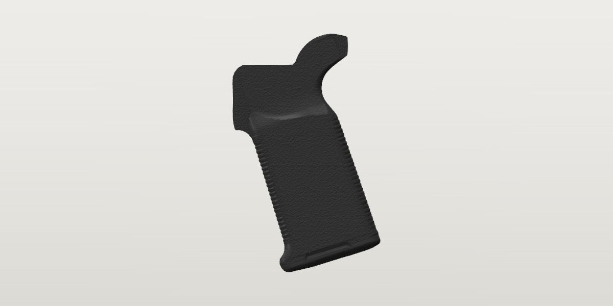
- Weight
- 3.1 oz Conflictpublished: Magpul, the maker, read Sep 30, 2026Its sources span 3.05 oz to 3.35 oz.
- Lowest price
- $20.15 at Primary Arms, read Nov 21, 2026 (Black)
- Maker's number
- MAG532
- Colours
- Black, FDE, ODG, Stealth Gray
- Drawn as
- modelled
In “22RB .22 LR rifle”, a build on the start page, as it is.
Its figures
Every figure the site draws and checks it by, with where it came from. Open one for each source's reading, and why one is used where they differ.
Grip angle from vertical17.9° ± 0.3°ConflictPhoto: black MOE-K2+, side view on white; supplied in chat, source not recorded
Published 17 deg
Magpul, the maker, read Sep 30, 2026 the page, from the project brief
Magpul does not say which line the angle is measured on.
Photo “grip straps measure 15.3° from vertical”
not yet archived, from the project brief
Scale: takedown, trigger and hammer pins. Read by strap lines fitted in the registered photo
Photo 15.74 deg ± 1.611 deg
MOE-K2+ installed on a mil-spec lower, straight right side, 1200 px; supplied in chat, from the site owner
Scale: frame from the reviewed holes takedown, selector, trigger, hammer (118.8 px/in, rms 0.056 in over 4 points); the frame's four picks disagree pair by pair (106 to 127 px/in) and the grip reads 10% large in it, so it gives a direction and no size. Read by mean lean of the fitted profile's edges in the band 0.45–0.85 of its height (rear 16.8°, front 14.7°) of the traced outline, fitted at a free scale (1.103, rms 0.050 in) to the grip's edges (tools/trace.py)
16.043 ± 1.588 until 2026-10-03, fitted at the scale of an outline that was 12% too large.
Photo 17.89 deg ± 0.3 deg used
black MOE-K2+, side view on white; supplied in chat, source not recorded, from the site owner
Scale: none needed: an angle within the outline. Read by the straps' lean from the flat top, the face that bears on the receiver's underside, in the photo as shot: the flat's straight stretch, columns 450 to 630 (the top edge to a tenth of a pixel in each), is a line sloping 0.12° down toward the front, rms 0.11 px; the straps' edges in the band 0.45–0.85 of the height lean 19.11° (rear) and 16.90° (front) from the photo's vertical, 18.00° in the mean. ± is the band chosen and the two straps' own 2.2° of taper.
16.04 until 2026-10-05, and the outline and the model turned 2° too upright with it: that reading turned the outline until a line through five points of its top was level, and one of the five was on the round of the block's front corner. The user's own grip, photographed on its side beside a tape (2d8cebb209a7, 6d81bb580120), has this outline's shape to 0.008 in at the median.
Photo 18.14 deg ± 0.5 deg
US D742,986 S, Magpul's design patent for the MOE-K2, FIG. 11 right side elevation, 300 dpi, harvested
Scale: none needed: an angle within the drawing. Read by the drawing's flat top is level on the page (0.04° over 480 columns); the outline's two edges in the band 0.45–0.85 of its height lean 19.02° (rear) and 17.26° (front) from its normal
The MOE-K2, of which the K2+ is the overmolded version: the same body. A design patent's drawing isn't to a stated scale, but an elevation keeps its angles.
Photo 18.5 deg ± 0.6 deg
MOE-K2+ installed on a mil-spec lower, straight right side, 1200 px; supplied in chat, from the site owner
Scale: none needed: an angle against the rifle's own level in the photo, which is turned 2.1 to 2.3° (the stock's top edge against the background rises 2.28° toward the muzzle over 220 columns, rms 0.09 px; the rail's four teeth in view rise 2.07°). Read by the straps' edges against the background in the band 0.45–0.85 of the grip's height lean 17.26° (rear) and 15.49° (front) from the photo's vertical, 19.4 and 17.6° from the rifle's; ± is the level's two readings and that neither edge is the bore's line
The same photo as installed-photo, read without the frame of four picks: the grip as it sits on a rifle.
Installed, the grip's flat top lies on the receiver's level underside, so the straps lean as they do from that face: an angle inside one photo, which no frame's scale touches. Magpul's patent elevation gives the same (18.1), and so does the grip on a rifle against the rifle's own level (18.5 ± 0.6); Magpul's 17° is the front strap's (16.8 to 17.3 in the three). The two older readings, 15.3 and 15.7 ± 1.6, were each made through a frame of receiver holes.
spec and strap-photo differ by 1.7° beyond what each states it is good to.
spec and flat-top differ by 0.9° beyond what each states it is good to.
spec and patent differ by 1.1° beyond what each states it is good to.
spec and installed-level differ by 1.5° beyond what each states it is good to.
strap-photo and flat-top differ by 2.6° beyond what each states it is good to.
strap-photo and patent differ by 2.8° beyond what each states it is good to.
strap-photo and installed-level differ by 3.2° beyond what each states it is good to.
installed-photo and flat-top differ by 2.2° beyond what each states it is good to.
installed-photo and patent differ by 2.4° beyond what each states it is good to.
installed-photo and installed-level differ by 2.8° beyond what each states it is good to.
Corrected on 2026-10-05, at the user's word to look at it: 16.04 until then. Found that afternoon while the grip was being seated on the Workhorse: on the outline as it was turned, the flat top rose 2° toward the front and the block's front face leaned as much, where Magpul's patent and the MOE-K2 in the MOE-guard photo have that face square to the top. Three sources were then read for the angle itself, each on its own (the photo as shot, the patent, the grip on a rifle): 17.9, 18.1 and 18.5.
“Receiver to bottom” (Magpul)4.1 in 104.1 mmConfirmedPublished: Magpul, the maker, read Sep 30, 2026
Published 4.1 in used
Magpul, the maker, read Sep 30, 2026 the page, from the project brief
Magpul's reference point isn't stated; the user's own grip measures 4.15 ± 0.03 from its flat top to its toe (bottom_below_lower_underside, 2026-10-03), so the receiver here is the face the grip's flat top bears on.
Grip bottom below the lower's underside at the grip4.15 in ± 0.03 in 105.4 mmConflictPhoto: the user's own MOE-K2+ on a tile floor, a tape on the floor beside it: its side, its back strap, its top; 2026-10-03
Photo 4.65 in
not yet archived, from the project brief
Scale: takedown, trigger and hammer pins. Read by registered to the lower by fitting the three pins; residuals ≤ 0.04 in
The brief's figure, from a photo never archived. On the user's own grip the beavertail's top to the toe is 4.72 and the flat top to the toe 4.15: this reads as the grip's overall height taken for its drop.
Photo 4.15 in ± 0.03 in used
the user's own MOE-K2+ on a tile floor, a tape on the floor beside it: its side, its back strap, its top; 2026-10-03, from the site owner
Scale: the tape in each photo (256.5, 347.4 and 315.4 px/in at the floor), each reading brought to the grip's own height above the floor by the lens's height: one height, about 35 in, fits all three views, whose edges stand 0.65, 1.4 to 2.15 and 3.15 to 4.2 in up. Read by The traced side outline (profiles.side) laid on the grip's silhouette in each view: it fits at 0.892 ± 0.006 of the size the 4.65 gave it (the tape alone, uncorrected, caps it at 0.907: lying on its side the grip spans 2.00 to 6.39 on the tape, where that outline spans 4.86). ± is the lens's height (32 to 60 in) and the height of the silhouette's edge. Read again by eye on the side photo: its top on the 2 in line, its toe at 6.39.
Magpul's own 'receiver to bottom', 4.1 (receiver_to_bottom, stated to one decimal), is this drop.
The user's own grip beside a tape, three views agreeing on one scale, and Magpul's 4.1 beside it. The brief's 4.65 made the grip 12% too large: its thickness then read 13% over Magpul's 1.2 on the patent's section, which was the same error.
photo and user-tape differ by 0.5 in beyond what each states it is good to.
Grip bottom in the rifle frame on the Workhorse, Y-5.22 in ± 0.032 in -132.6 mmProvisionalWorked out: {bad-workhorse-lower.grip_seat_y} - {.bottom_below_lower_underside}
Worked out -5.2195 in used
{bad-workhorse-lower.grip_seat_y} - {.bottom_below_lower_underside}, harvested
The drop from the grip's seat: 4.15 by the user's own grip (2026-10-03; the id is from when the drop was the brief's 4.65). The installed photo that seemed to support 4.65 is framed by four picks that disagree with each other (106 to 127 px/in between pairs).
Worked out -5.1695 in ± 0.05 in
{bad-workhorse-lower.grip_seat_y} - {.receiver_to_bottom}, harvested
Magpul's 4.1 in 'receiver to bottom', from the face the grip's flat top bears on (it had been read from the shelf's lower-front end, -6.116, while the drop was thought to be 4.65).
The drop measured on the user's own grip, from the seat the lower gives; Magpul's 4.1, stated to one decimal, agrees.
From the grip's seat (bad-workhorse-lower.grip_seat_y). M2 hung the grip from grip_shelf_top_y (the bottom of the lower's step, 0.38 in lower), which put the bottom at −6.21; until 2026-10-03 the drop was the brief's 4.65 and the bottom −5.746; until 2026-10-05 the seat was 0.027 lower (the Workhorse's underside as a two-pin frame read it), and the bottom −5.246. Magpul's 'receiver to bottom', read from the same seat, agrees with the user's own grip.
Overall height in the grip frame (the beavertail's top to the toe)4.773 in ± 0.05 in 121.2 mmProvisionalPhoto: black MOE-K2+, side view on white; supplied in chat, source not recorded
Photo 4.773 in ± 0.05 in used
black MOE-K2+, side view on white; supplied in chat, source not recorded, from the site owner
Scale: the 4.15 in drop (magpul-moe-k2-plus.bottom_below_lower_underside), from the flat top's rear end to the toe (948 px, 228.5 px/in). Read by height of the traced outline, the beavertail's top to the toe (tools/trace.py target), with the flat top level
4.733 until 2026-10-05, with the outline turned 2° too upright (grip_angle): the beavertail's tip, an inch behind the flat, stands 0.04 in higher over it when the flat is level. 5.292 while the drop was the brief's 4.65. On the user's own grip beside a tape the span read 4.72 ± 0.03 with the outline as it was turned then: the same grip, 4.76 in this frame.
What the end section from Magpul's patent is scaled to (orthographic views share their height).
Toe (the grip's lowest point), Y in the grip frame-4.15 in ± 0.03 in -105.4 mmProvisionalWorked out: -{.bottom_below_lower_underside}
Worked out -4.15 in used
-{.bottom_below_lower_underside}, harvested
Where the traced end section's toe sits, so it lines up with the side profile's.
Thickness1.2 in 30.5 mmConfirmedPublished: Magpul, the maker, read Sep 30, 2026
Published 1.2 in used
Magpul, the maker, read Sep 30, 2026 the page, from the project brief
Photo 1.223 in ± 0.03 in
US D742,986 S, Magpul's design patent for the MOE-K2, FIG. 12 front elevation, 300 dpi, harvested
Scale: the traced side's overall height (magpul-moe-k2-plus.overall_height, 4.773 in, with the side's flat top level as the patent draws it): orthographic views share their height. Read by widest row of the traced front elevation, at the base's flare (tools/trace.py target)
Magpul's own drawing, scaled by our side outline. 1.213 while that outline was turned 2° too upright and 0.04 in shorter for it (until 2026-10-05); 1.356 while it was scaled by the brief's 4.65 drop: the conflict with Magpul's 1.2 was the drop's (bottom_below_lower_underside), as this note had half said (scaled by Magpul's 4.1 the section gave ~1.22).
Photo 1.195 in ± 0.02 in
the user's own MOE-K2+ lying on its front strap, twice, and standing on its base, a tape on the floor beside it; 2026-10-03, from the site owner
Scale: the tape in each photo, brought to the body's widest (1.0 and 2.8 in above the floor) by the lens's height, 35 to 37 in (bottom_below_lower_underside's method). Read by the body's two edges at its widest: 1.190, 1.198 and 1.196 in the three photos; ± is the lens's height (± 5 in) and where on the section the widest point stands (± 0.3 in)
Magpul's published figure, which the user's own grip measures (1.195 ± 0.02). The patent's section read 13% wider only while the side outline it is scaled to was 12% too large (bottom_below_lower_underside).
Top block, across, just below the face that meets the receiver0.88 in ± 0.02 in 22.4 mmProvisionalPhoto: the user's own MOE-K2+ lying on its front strap, its back strap straight on, a tape on the floor beside it; 2026-10-03
Photo 0.88 in ± 0.02 in used
the user's own MOE-K2+ lying on its front strap, its back strap straight on, a tape on the floor beside it; 2026-10-03, from the site owner
Scale: the tape (347.4 px/in at the floor), brought up to the block's edges, 2.4 in above the floor, by the lens's height (37 in: bottom_below_lower_underside's method). Read by the block's two edges below the beavertail's horns, columns 1167 and 1492 at row 643: 0.9384 on the tape, 0.878 at their height (0.859 to 0.891). The silhouette there is the block's sides and the beavertail's root together.
At the face itself it is 0.853 ± 0.015 (the top seen from above, 45eafc02ec88: its two straight edges, 4.0 to 4.2 in above the floor from 35 in); the patent's front elevation at the side's height has 0.885.
The slot in the top that goes over the receiver's lug, across0.425 in ± 0.02 in 10.8 mmProvisionalPhoto: the user's own MOE-K2+ standing on its base, its top straight on from above, a tape on the floor beside it; 2026-10-03
Photo 0.425 in ± 0.02 in used
the user's own MOE-K2+ standing on its base, its top straight on from above, a tape on the floor beside it; 2026-10-03, from the site owner
Scale: the top face's own width in the same rows, 0.853 ± 0.015 (top_block_width's note: the face's two straight edges, by the tape and the lens's height). Read by the slot's two walls and the face's two edges on 350 rows (985 to 1334 of the photo): the slot is 0.499 of the face (0.483 to 0.506, the rows' 10th to 90th percentile; 151.8 px of 304.7), and centred on it within 0.002 in. Both lie in the face's plane, so their ratio is free of the lens's height. ± is the face's own and the rows' spread. The edges found were looked at on the photo.
The receiver's lug is .375 wide (std.ar15.grip_lug_width): 0.025 clear on each side. In plan the slot runs from a rear wall under the flat top's rear end to the nose's front face, which it is cut through, 1.44 to 1.47 in: where the standard lug's rear face and the trigger guard's ears stand, as near as a view whose ends are at different heights places them (0.06 in). A shallow step round its mouth (0.55 across), the screw's hole and the storage core's opening in its floor aren't measured.
Back strap, across its ribbed face (between where it rounds into the sides)0.75 in ± 0.05 in 19 mmProvisionalPhoto: the user's own MOE-K2+ lying on its front strap, its back strap straight on; 2026-10-03
Photo 0.75 in ± 0.05 in used
the user's own MOE-K2+ lying on its front strap, its back strap straight on; 2026-10-03, from the site owner
Scale: the body's width in the same view (thickness). Read by the ribs run 0.7 to 0.8 in across the back strap, the body 1.2: what is left either side is where the strap rounds into the side
Front-to-back depth at mid-height (perpendicular to the straps)1.928 in ± 0.107 in 49 mmCorroboratedPhoto: Wing Tactical, ODG MOE-K2+, near-straight side view on white
Photo 1.928 in ± 0.107 in used
Wing Tactical, ODG MOE-K2+, near-straight side view on white, harvested
Scale: the grip's drop from the lower's shelf (upper-rear end) to its lowest point, 4.15 in (magpul-moe-k2-plus.bottom_below_lower_underside: the user's own grip, 2026-10-03; these picks were first scaled by the brief's 4.65, 225.8 px/in) = 1050 px, i.e. 253.0 px/in; origin at the rear end of the grip's flat top (the shelf's upper-rear end). Read by edge points picked on a gridded view (±10 px); photo vertical taken as installed vertical, because its straps average 16.4° from vertical, matching the 15.3–17° grip angle
Photo 1.81 in ± 0.1 in
black MOE-K2+, side view on white; supplied in chat, source not recorded, from the site owner
Scale: the 4.15 in drop (magpul-moe-k2-plus.bottom_below_lower_underside) = 948 px, i.e. 228.5 px/in, after rotating the outline to the adopted grip angle. Read by horizontal width at 2.56 in below the shelf (the Wing Tactical photo's mid-height station) × cos(grip angle), from the traced outline (tools/trace.py target); ± covers the station and the straps' 2° convergence
Re-derived 2026-09-30 by tools/trace.py. The prototype trace had rotated the photo the wrong way (straps at 20.4° instead of 15.3°), which inflated this to 2.13.
Two independent side photos agree within their ± (1.93 ± 0.11 and 1.80 ± 0.10, 7% apart; both rescaled on 2026-10-03 from the 4.65 drop to the 4.15 the user's own grip measures); the Wing Tactical reading is kept. Nothing renders from this value: the grip is drawn from the traced outline (profiles.side, black photo).
The user sent the plain MOE-K2 version of this Wing Tactical shot (same shape, no rubber overmold); the harvested K2+ one is used.
Profile: back strap at the shelf level, X (grip frame)-0.352 in ± 0.045 in -8.9 mmProvisionalPhoto: Wing Tactical, ODG MOE-K2+, near-straight side view on white
Photo -0.352 in ± 0.045 in used
Wing Tactical, ODG MOE-K2+, near-straight side view on white, harvested
Scale: the grip's drop from the lower's shelf (upper-rear end) to its lowest point, 4.15 in (magpul-moe-k2-plus.bottom_below_lower_underside: the user's own grip, 2026-10-03; these picks were first scaled by the brief's 4.65, 225.8 px/in) = 1050 px, i.e. 253.0 px/in; origin at the rear end of the grip's flat top (the shelf's upper-rear end). Read by edge points picked on a gridded view (±10 px); photo vertical taken as installed vertical, because its straps average 16.4° from vertical, matching the 15.3–17° grip angle
The back-strap line extended up to the shelf level; the beavertail and web above it come with the M3 trace.
Profile: front strap at the shelf level, X (grip frame)1.146 in ± 0.045 in 29.1 mmProvisionalPhoto: Wing Tactical, ODG MOE-K2+, near-straight side view on white
Photo 1.146 in ± 0.045 in used
Wing Tactical, ODG MOE-K2+, near-straight side view on white, harvested
Scale: the grip's drop from the lower's shelf (upper-rear end) to its lowest point, 4.15 in (magpul-moe-k2-plus.bottom_below_lower_underside: the user's own grip, 2026-10-03; these picks were first scaled by the brief's 4.65, 225.8 px/in) = 1050 px, i.e. 253.0 px/in; origin at the rear end of the grip's flat top (the shelf's upper-rear end). Read by edge points picked on a gridded view (±10 px); photo vertical taken as installed vertical, because its straps average 16.4° from vertical, matching the 15.3–17° grip angle
Profile: rear-bottom corner, X (grip frame)-1.759 in ± 0.045 in -44.7 mmProvisionalPhoto: Wing Tactical, ODG MOE-K2+, near-straight side view on white
Photo -1.759 in ± 0.045 in used
Wing Tactical, ODG MOE-K2+, near-straight side view on white, harvested
Scale: the grip's drop from the lower's shelf (upper-rear end) to its lowest point, 4.15 in (magpul-moe-k2-plus.bottom_below_lower_underside: the user's own grip, 2026-10-03; these picks were first scaled by the brief's 4.65, 225.8 px/in) = 1050 px, i.e. 253.0 px/in; origin at the rear end of the grip's flat top (the shelf's upper-rear end). Read by edge points picked on a gridded view (±10 px); photo vertical taken as installed vertical, because its straps average 16.4° from vertical, matching the 15.3–17° grip angle
Profile: rear-bottom corner, Y (grip frame)-3.565 in ± 0.045 in -90.6 mmProvisionalPhoto: Wing Tactical, ODG MOE-K2+, near-straight side view on white
Photo -3.565 in ± 0.045 in used
Wing Tactical, ODG MOE-K2+, near-straight side view on white, harvested
Scale: the grip's drop from the lower's shelf (upper-rear end) to its lowest point, 4.15 in (magpul-moe-k2-plus.bottom_below_lower_underside: the user's own grip, 2026-10-03; these picks were first scaled by the brief's 4.65, 225.8 px/in) = 1050 px, i.e. 253.0 px/in; origin at the rear end of the grip's flat top (the shelf's upper-rear end). Read by edge points picked on a gridded view (±10 px); photo vertical taken as installed vertical, because its straps average 16.4° from vertical, matching the 15.3–17° grip angle
Profile: front-bottom corner, X (grip frame)0.296 in ± 0.045 in 7.5 mmProvisionalPhoto: Wing Tactical, ODG MOE-K2+, near-straight side view on white
Photo 0.296 in ± 0.045 in used
Wing Tactical, ODG MOE-K2+, near-straight side view on white, harvested
Scale: the grip's drop from the lower's shelf (upper-rear end) to its lowest point, 4.15 in (magpul-moe-k2-plus.bottom_below_lower_underside: the user's own grip, 2026-10-03; these picks were first scaled by the brief's 4.65, 225.8 px/in) = 1050 px, i.e. 253.0 px/in; origin at the rear end of the grip's flat top (the shelf's upper-rear end). Read by edge points picked on a gridded view (±10 px); photo vertical taken as installed vertical, because its straps average 16.4° from vertical, matching the 15.3–17° grip angle
Profile: front-bottom corner, Y (grip frame)-4.127 in ± 0.045 in -104.8 mmProvisionalPhoto: Wing Tactical, ODG MOE-K2+, near-straight side view on white
Photo -4.127 in ± 0.045 in used
Wing Tactical, ODG MOE-K2+, near-straight side view on white, harvested
Scale: the grip's drop from the lower's shelf (upper-rear end) to its lowest point, 4.15 in (magpul-moe-k2-plus.bottom_below_lower_underside: the user's own grip, 2026-10-03; these picks were first scaled by the brief's 4.65, 225.8 px/in) = 1050 px, i.e. 253.0 px/in; origin at the rear end of the grip's flat top (the shelf's upper-rear end). Read by edge points picked on a gridded view (±10 px); photo vertical taken as installed vertical, because its straps average 16.4° from vertical, matching the 15.3–17° grip angle
Top block's foremost point, ahead of the flat top's rear end (the grip's half of its seat)1.33 in ± 0.012 in 33.8 mmProvisionalPhoto: black MOE-K2+, side view on white; supplied in chat, source not recorded
Photo 1.33 in ± 0.012 in used
black MOE-K2+, side view on white; supplied in chat, source not recorded, from the site owner
Scale: scale from magpul-moe-k2-plus.bottom_below_lower_underside = 4.15 in (y from the origin to the far edge 948 px → 228.5 px/in). Read by x_max in y [-1.26, -0.2] of the traced outline (tools/trace.py); the top block's foremost point ahead of the flat top's rear end: on its front face, which is straight (a line through 0.88 in of it lies 0.004 in behind this, rms 0.003) and 0.3° from square to the flat top
What of the grip comes nearest the rear face of the trigger guard's ears: seat_x puts it there. The face is flat and square to the top (Magpul's patent elevation, the MOE-K2 in the MOE-guard photo to within a pixel, and this outline since 2026-10-05). Until then the outline was turned 2° too upright (grip_angle), the face leaned on it, and this was its foot, 1.289 from an origin 0.067 in further forward: the flat top's rear end is found where the top leaves the flat's level by 4 px, and on a flat that rose toward the front that was short of the beavertail's curve.
Seat, X: where the grip's frame origin (its flat top's rear end) sits ahead of the takedown pin, installed-0.155 in ± 0.012 in -3.9 mmConflictWorked out: {std.ar15.receiver_rear_x} + {std.ar15.grip_lug_front_from_rear_face} - {.block_front_x}
Worked out -0.155 in ± 0.012 in used
{std.ar15.receiver_rear_x} + {std.ar15.grip_lug_front_from_rear_face} - {.block_front_x}, harvested
(-0.114 until 2026-10-05, for the same place on the grip: the frame's origin is 0.067 in further back on it since the outline was turned to its flat top, block_front_x.) The top block's foremost point (block_front_x, on the traced side) on the rear face of the trigger guard's ears, where the Army drawing ends the lug (2.300 from the receiver's rear face, 1.175 ahead of the takedown pin). That the two meet is read where they do, in the MOE-guard photo (a MOE-K2 on a mil-spec lower, a copy on file): the seam between the block's front face and the lower is one dark line 2 to 3 px wide (0.012 in at most, at 258 px/in), straight from the receiver's underside down to the ears' foot and square to the pin line within 0.5°; the photo's frame has it 1.167 ahead of the pin and the rear guard screw beside it 1.181 (82 px behind its centre), either side of the drawing's 1.175.
Photo -0.11 in ± 0.05 in
MOE guard and MOE-K2 installed on a mil-spec lower, close right side, 1222 px; supplied in chat, from the site owner
Scale: frame from the reviewed holes selector, trigger, rear_ear, front_ear (258.3 px/in, rms 0.011 in over 4 points). Read by x of the fitted profile's origin of the traced outline (tools/trace.py); the traced K2+ outline, its flat top on the receiver's underside, slid along x until its front strap matches the photo's (43 rows below the lower)
-0.097 with the outline turned 2° too upright and its origin 0.067 in further forward (2026-10-05, earlier the same day); -0.128 before that, and the adopted seat until then: the frame's four places are the Workhorse's ledger values, and its two guard holes were that lower's own traced ones, the front one 0.042 in low (a frame of its two pins alone: bad-workhorse-lower.trigger_guard_front_y). At the drawing's places the four features fit to 0.011 in rms where they had fitted to 0.019, the receiver's underside is 0.024 higher (grip_mating_y), and the same 43 rows put the grip 0.031 further forward: the foot of its block's front face 0.017 past the ears' rear face, which a grip can't be, and which is inside this reading's ±. The rows leave a trend, 0.027 in per inch: the photo's front strap leans 16.7° in its frame and the outline's 15.3° over the same rows (the outline is turned 2° too upright: grip_angle), so a strap matched 1.5 to 2.3 in below the block can't place the block. (-0.291 until 2026-10-03, when the outline slid onto the strap was 12% too large, the 4.65 drop; at its size the rows match to 0.026 in, 10–90%.)
Photo 0.121 in ± 0.05 in
MOE-K2+ installed on a mil-spec lower, straight right side, 1200 px; supplied in chat, from the site owner
Scale: frame from the reviewed holes takedown, selector, trigger, hammer (118.8 px/in, rms 0.056 in over 4 points). Read by x of the fitted profile's origin of the traced outline (tools/trace.py); the traced outline's origin (its flat top's rear end), fitted by rotation and translation (at the outline's own scale) to the grip's edges against the background
Read with the outline 12% too large (2026-10-03: the drop is 4.15, not 4.65), in a frame whose four picks disagree pair by pair (106 to 127 px/in) and in which the grip reads 10% large: the frame places nothing. Kept as read; the fit is now made at a free scale for the lean alone.
Where the grip stops is where it touches: the photo shows the block's front face on the lower's, a seam of 0.012 in at most, at the place the drawing gives the ears' rear face within 0.006 in. The strap matched through the photo's frame agrees within its ± (0.045 in further forward, ± 0.05) and can't say more: it moved 0.031 in with two of the frame's four places.
interface and k2-installed differ by 0.276 in beyond what each states it is good to.
guard-photo and k2-installed differ by 0.231 in beyond what each states it is good to.
A grip's own figure on the standard AR-15 grip mount: the lower gives the height (its underside, grip_seat_y), the grip says where its origin lands fore-aft. It was bad-workhorse-lower.grip_seat_x until M6. Seated by its interface since 2026-10-05, as the BCM grip is: the top block's front on the rear face of the trigger guard's ears, which is how the MOE-guard photo shows a K2 sitting (the seam between them, read where it is). Until then it was that photo's front strap matched through a frame of four features, -0.128, which changed by 0.031 in when the frame's guard holes went from the Workhorse's traced places to the drawing's: a seat read 1.5 in below the lower through a frame is as good as the frame, and the frame was the Workhorse's. The Magpul K2+ product photo (its takedown-pin pick 0.17 in off) put it 0.42 in forward, into the ear; that reading stays as a visible conflict.
Relief under the top block: its upper edge's rear end, X-0.162 in ± 0.012 in -4.1 mmProvisionalPhoto: US D742,986 S, Magpul's design patent for the MOE-K2, FIG. 11 right side elevation, 300 dpi
Photo -0.162 in ± 0.012 in used
US D742,986 S, Magpul's design patent for the MOE-K2, FIG. 11 right side elevation, 300 dpi, harvested
Scale: the grip's own traced side outline (profiles.side, scaled by the 4.15 in drop) laid on the drawing's outer line: 502.6 px/in, turned 0.02 deg, the two 0.012 in apart at the median and 0.029 at the 90th percentile (the K2 of the drawing against the K2+ of the outline, and the line's own width). Read by where the drawing's ink lies along columns every tenth of an inch from x -0.3 to 1.2 and rows from y 0.3 to -1.1, in the grip's frame: the upper edge is a straight line, y -0.489 at x -0.15, -0.514 at 0, -0.545 at 0.2, -0.577 at 0.4, -0.609 at 0.6, -0.642 at 0.8, -0.666 at 0.95 (9.1 degrees down toward the front, each within 0.002 of the line), from the back strap's blend line at x -0.162 (rows -0.5 to -0.7) to where the floor's lower edge comes up to it at x 0.995. ± is the fit's and the line's width
The grip's sides between the top block (0.88 across) and the body (1.2) are a relief swept in a curve: a floor that leaves the block's side along a straight upper edge, and under it a steeper band whose lower edge is the line the grip is known by after its outline. Magpul's patent draws the three lines (the upper edge, the floor's lower edge, the relief's lower edge); the user's own grip and a seller's FDE one have the band where the patent has it (relief_floor_low_y). Until 2026-10-13 the model had a straight shoulder square to the strap there.
Relief under the top block: its upper edge's rear end, Y-0.487 in ± 0.012 in -12.4 mmProvisionalPhoto: US D742,986 S, Magpul's design patent for the MOE-K2, FIG. 11 right side elevation, 300 dpi
Photo -0.487 in ± 0.012 in used
US D742,986 S, Magpul's design patent for the MOE-K2, FIG. 11 right side elevation, 300 dpi, harvested
Scale: the grip's own traced side outline (profiles.side, scaled by the 4.15 in drop) laid on the drawing's outer line: 502.6 px/in, turned 0.02 deg, the two 0.012 in apart at the median and 0.029 at the 90th percentile (the K2 of the drawing against the K2+ of the outline, and the line's own width). Read by where the drawing's ink lies along columns every tenth of an inch from x -0.3 to 1.2 and rows from y 0.3 to -1.1, in the grip's frame: the upper edge is a straight line, y -0.489 at x -0.15, -0.514 at 0, -0.545 at 0.2, -0.577 at 0.4, -0.609 at 0.6, -0.642 at 0.8, -0.666 at 0.95 (9.1 degrees down toward the front, each within 0.002 of the line), from the back strap's blend line at x -0.162 (rows -0.5 to -0.7) to where the floor's lower edge comes up to it at x 0.995. ± is the fit's and the line's width
Relief under the top block: its upper edge's front end, X0.995 in ± 0.015 in 25.3 mmProvisionalPhoto: US D742,986 S, Magpul's design patent for the MOE-K2, FIG. 11 right side elevation, 300 dpi
Photo 0.995 in ± 0.015 in used
US D742,986 S, Magpul's design patent for the MOE-K2, FIG. 11 right side elevation, 300 dpi, harvested
Scale: the grip's own traced side outline (profiles.side, scaled by the 4.15 in drop) laid on the drawing's outer line: 502.6 px/in, turned 0.02 deg, the two 0.012 in apart at the median and 0.029 at the 90th percentile (the K2 of the drawing against the K2+ of the outline, and the line's own width). Read by where the drawing's ink lies along columns every tenth of an inch from x -0.3 to 1.2 and rows from y 0.3 to -1.1, in the grip's frame: the upper edge is a straight line, y -0.489 at x -0.15, -0.514 at 0, -0.545 at 0.2, -0.577 at 0.4, -0.609 at 0.6, -0.642 at 0.8, -0.666 at 0.95 (9.1 degrees down toward the front, each within 0.002 of the line), from the back strap's blend line at x -0.162 (rows -0.5 to -0.7) to where the floor's lower edge comes up to it at x 0.995. ± is the fit's and the line's width
Relief under the top block: its upper edge's front end, Y-0.673 in ± 0.012 in -17.1 mmProvisionalPhoto: US D742,986 S, Magpul's design patent for the MOE-K2, FIG. 11 right side elevation, 300 dpi
Photo -0.673 in ± 0.012 in used
US D742,986 S, Magpul's design patent for the MOE-K2, FIG. 11 right side elevation, 300 dpi, harvested
Scale: the grip's own traced side outline (profiles.side, scaled by the 4.15 in drop) laid on the drawing's outer line: 502.6 px/in, turned 0.02 deg, the two 0.012 in apart at the median and 0.029 at the 90th percentile (the K2 of the drawing against the K2+ of the outline, and the line's own width). Read by where the drawing's ink lies along columns every tenth of an inch from x -0.3 to 1.2 and rows from y 0.3 to -1.1, in the grip's frame: the upper edge is a straight line, y -0.489 at x -0.15, -0.514 at 0, -0.545 at 0.2, -0.577 at 0.4, -0.609 at 0.6, -0.642 at 0.8, -0.666 at 0.95 (9.1 degrees down toward the front, each within 0.002 of the line), from the back strap's blend line at x -0.162 (rows -0.5 to -0.7) to where the floor's lower edge comes up to it at x 0.995. ± is the fit's and the line's width
Relief: the floor's lower edge (where the steeper band begins), its rear end, X-0.18 in ± 0.015 in -4.6 mmProvisionalPhoto: US D742,986 S, Magpul's design patent for the MOE-K2, FIG. 11 right side elevation, 300 dpi
Photo -0.18 in ± 0.015 in used
US D742,986 S, Magpul's design patent for the MOE-K2, FIG. 11 right side elevation, 300 dpi, harvested
Scale: the grip's own traced side outline (profiles.side, scaled by the 4.15 in drop) laid on the drawing's outer line: 502.6 px/in, turned 0.02 deg, the two 0.012 in apart at the median and 0.029 at the 90th percentile (the K2 of the drawing against the K2+ of the outline, and the line's own width). Read by where the drawing's ink lies along columns every tenth of an inch from x -0.3 to 1.2 and rows from y 0.3 to -1.1, in the grip's frame: the upper edge is a straight line, y -0.489 at x -0.15, -0.514 at 0, -0.545 at 0.2, -0.577 at 0.4, -0.609 at 0.6, -0.642 at 0.8, -0.666 at 0.95 (9.1 degrees down toward the front, each within 0.002 of the line), from the back strap's blend line at x -0.162 (rows -0.5 to -0.7) to where the floor's lower edge comes up to it at x 0.995. ± is the fit's and the line's width
The floor's lower edge is an arc: through its rear end, its lowest point and its front point a circle of 0.854 in lies within 0.013 in of the drawing's line at every column read (y -0.806 at x -0.15, -0.889 at 0, -0.931 at 0.1, -0.960 at 0.2, -0.980 at 0.3, -0.985 at 0.4, -0.980 at 0.5, -0.959 at 0.6, -0.924 at 0.7, -0.876 at 0.8, -0.804 at 0.9, -0.756 at 0.95). Ahead of its front point it turns up to the upper edge's front end.
Relief: the floor's lower edge, its rear end, Y-0.787 in ± 0.012 in -20 mmProvisionalPhoto: US D742,986 S, Magpul's design patent for the MOE-K2, FIG. 11 right side elevation, 300 dpi
Photo -0.787 in ± 0.012 in used
US D742,986 S, Magpul's design patent for the MOE-K2, FIG. 11 right side elevation, 300 dpi, harvested
Scale: the grip's own traced side outline (profiles.side, scaled by the 4.15 in drop) laid on the drawing's outer line: 502.6 px/in, turned 0.02 deg, the two 0.012 in apart at the median and 0.029 at the 90th percentile (the K2 of the drawing against the K2+ of the outline, and the line's own width). Read by where the drawing's ink lies along columns every tenth of an inch from x -0.3 to 1.2 and rows from y 0.3 to -1.1, in the grip's frame: the upper edge is a straight line, y -0.489 at x -0.15, -0.514 at 0, -0.545 at 0.2, -0.577 at 0.4, -0.609 at 0.6, -0.642 at 0.8, -0.666 at 0.95 (9.1 degrees down toward the front, each within 0.002 of the line), from the back strap's blend line at x -0.162 (rows -0.5 to -0.7) to where the floor's lower edge comes up to it at x 0.995. ± is the fit's and the line's width
Relief: the floor's lower edge, its lowest point, X0.4 in ± 0.05 in 10.2 mmProvisionalPhoto: US D742,986 S, Magpul's design patent for the MOE-K2, FIG. 11 right side elevation, 300 dpi
Photo 0.4 in ± 0.05 in used
US D742,986 S, Magpul's design patent for the MOE-K2, FIG. 11 right side elevation, 300 dpi, harvested
Scale: the grip's own traced side outline (profiles.side, scaled by the 4.15 in drop) laid on the drawing's outer line: 502.6 px/in, turned 0.02 deg, the two 0.012 in apart at the median and 0.029 at the 90th percentile (the K2 of the drawing against the K2+ of the outline, and the line's own width). Read by where the drawing's ink lies along columns every tenth of an inch from x -0.3 to 1.2 and rows from y 0.3 to -1.1, in the grip's frame: the upper edge is a straight line, y -0.489 at x -0.15, -0.514 at 0, -0.545 at 0.2, -0.577 at 0.4, -0.609 at 0.6, -0.642 at 0.8, -0.666 at 0.95 (9.1 degrees down toward the front, each within 0.002 of the line), from the back strap's blend line at x -0.162 (rows -0.5 to -0.7) to where the floor's lower edge comes up to it at x 0.995. ± is the fit's and the line's width
Flat there: within 0.005 of its lowest from x 0.3 to 0.5.
Relief: the floor's lower edge, its lowest point, Y-0.985 in ± 0.01 in -25 mmProvisionalPhoto: US D742,986 S, Magpul's design patent for the MOE-K2, FIG. 11 right side elevation, 300 dpi
Photo -0.985 in ± 0.01 in used
US D742,986 S, Magpul's design patent for the MOE-K2, FIG. 11 right side elevation, 300 dpi, harvested
Scale: the grip's own traced side outline (profiles.side, scaled by the 4.15 in drop) laid on the drawing's outer line: 502.6 px/in, turned 0.02 deg, the two 0.012 in apart at the median and 0.029 at the 90th percentile (the K2 of the drawing against the K2+ of the outline, and the line's own width). Read by where the drawing's ink lies along columns every tenth of an inch from x -0.3 to 1.2 and rows from y 0.3 to -1.1, in the grip's frame: the upper edge is a straight line, y -0.489 at x -0.15, -0.514 at 0, -0.545 at 0.2, -0.577 at 0.4, -0.609 at 0.6, -0.642 at 0.8, -0.666 at 0.95 (9.1 degrees down toward the front, each within 0.002 of the line), from the back strap's blend line at x -0.162 (rows -0.5 to -0.7) to where the floor's lower edge comes up to it at x 0.995. ± is the fit's and the line's width
Where the user's own grip and the FDE one have it: on the FDE photo (5aa8d0d21f23, the outline laid on it to 0.003 in) the tone down each column rises through the floor and is brightest between this edge and the relief's lower edge, at y -0.94 (x 0), -1.00 (0.2), -1.03 (0.4), -1.00 (0.6), -0.93 (0.8), and falls back within a tenth of an inch below it; on the user's own grip (2d8cebb209a7, from above with a tape beside it) the dark arc of the floor's deepest shade runs y -0.85 (x 0), -0.94 (0.17), -0.965 (0.37), -0.94 (0.57), -0.85 (0.77), 0.02 to 0.03 above this line all along.
Relief: the floor's lower edge, where it turns up to meet the upper edge, X0.95 in ± 0.015 in 24.1 mmProvisionalPhoto: US D742,986 S, Magpul's design patent for the MOE-K2, FIG. 11 right side elevation, 300 dpi
Photo 0.95 in ± 0.015 in used
US D742,986 S, Magpul's design patent for the MOE-K2, FIG. 11 right side elevation, 300 dpi, harvested
Scale: the grip's own traced side outline (profiles.side, scaled by the 4.15 in drop) laid on the drawing's outer line: 502.6 px/in, turned 0.02 deg, the two 0.012 in apart at the median and 0.029 at the 90th percentile (the K2 of the drawing against the K2+ of the outline, and the line's own width). Read by where the drawing's ink lies along columns every tenth of an inch from x -0.3 to 1.2 and rows from y 0.3 to -1.1, in the grip's frame: the upper edge is a straight line, y -0.489 at x -0.15, -0.514 at 0, -0.545 at 0.2, -0.577 at 0.4, -0.609 at 0.6, -0.642 at 0.8, -0.666 at 0.95 (9.1 degrees down toward the front, each within 0.002 of the line), from the back strap's blend line at x -0.162 (rows -0.5 to -0.7) to where the floor's lower edge comes up to it at x 0.995. ± is the fit's and the line's width
Relief: the floor's lower edge, where it turns up to meet the upper edge, Y-0.756 in ± 0.012 in -19.2 mmProvisionalPhoto: US D742,986 S, Magpul's design patent for the MOE-K2, FIG. 11 right side elevation, 300 dpi
Photo -0.756 in ± 0.012 in used
US D742,986 S, Magpul's design patent for the MOE-K2, FIG. 11 right side elevation, 300 dpi, harvested
Scale: the grip's own traced side outline (profiles.side, scaled by the 4.15 in drop) laid on the drawing's outer line: 502.6 px/in, turned 0.02 deg, the two 0.012 in apart at the median and 0.029 at the 90th percentile (the K2 of the drawing against the K2+ of the outline, and the line's own width). Read by where the drawing's ink lies along columns every tenth of an inch from x -0.3 to 1.2 and rows from y 0.3 to -1.1, in the grip's frame: the upper edge is a straight line, y -0.489 at x -0.15, -0.514 at 0, -0.545 at 0.2, -0.577 at 0.4, -0.609 at 0.6, -0.642 at 0.8, -0.666 at 0.95 (9.1 degrees down toward the front, each within 0.002 of the line), from the back strap's blend line at x -0.162 (rows -0.5 to -0.7) to where the floor's lower edge comes up to it at x 0.995. ± is the fit's and the line's width
Relief: the band between the floor's lower edge and the relief's lower edge, at its lowest0.119 in ± 0.01 in 3 mmProvisionalPhoto: US D742,986 S, Magpul's design patent for the MOE-K2, FIG. 11 right side elevation, 300 dpi
Photo 0.119 in ± 0.01 in used
US D742,986 S, Magpul's design patent for the MOE-K2, FIG. 11 right side elevation, 300 dpi, harvested
Scale: the grip's own traced side outline (profiles.side, scaled by the 4.15 in drop) laid on the drawing's outer line: 502.6 px/in, turned 0.02 deg, the two 0.012 in apart at the median and 0.029 at the 90th percentile (the K2 of the drawing against the K2+ of the outline, and the line's own width). Read by where the drawing's ink lies along columns every tenth of an inch from x -0.3 to 1.2 and rows from y 0.3 to -1.1, in the grip's frame: the upper edge is a straight line, y -0.489 at x -0.15, -0.514 at 0, -0.545 at 0.2, -0.577 at 0.4, -0.609 at 0.6, -0.642 at 0.8, -0.666 at 0.95 (9.1 degrees down toward the front, each within 0.002 of the line), from the back strap's blend line at x -0.162 (rows -0.5 to -0.7) to where the floor's lower edge comes up to it at x 0.995. ± is the fit's and the line's width
The relief's lower edge runs beside the floor's from x 0.2 forward (0.128 under it at x 0.2, 0.119 at 0.4, 0.117 at 0.5, 0.119 at 0.6, 0.115 at 0.8, 0.127 at 0.9: a circle about the same centre, this much larger, is within 0.016 in of the drawing's line from x 0.1 to 0.95), and behind that leaves it for the back strap in a straight line (relief_edge_rear_x). Ahead of x 0.95 it climbs the nose toward the block's upper front corner, beside the block's own front edge: not drawn (the nose is the three-view hull it was).
Relief: its lower edge's rear end, at the back strap's blend, X-0.3 in ± 0.02 in -7.6 mmProvisionalPhoto: US D742,986 S, Magpul's design patent for the MOE-K2, FIG. 11 right side elevation, 300 dpi
Photo -0.3 in ± 0.02 in used
US D742,986 S, Magpul's design patent for the MOE-K2, FIG. 11 right side elevation, 300 dpi, harvested
Scale: the grip's own traced side outline (profiles.side, scaled by the 4.15 in drop) laid on the drawing's outer line: 502.6 px/in, turned 0.02 deg, the two 0.012 in apart at the median and 0.029 at the 90th percentile (the K2 of the drawing against the K2+ of the outline, and the line's own width). Read by where the drawing's ink lies along columns every tenth of an inch from x -0.3 to 1.2 and rows from y 0.3 to -1.1, in the grip's frame: the upper edge is a straight line, y -0.489 at x -0.15, -0.514 at 0, -0.545 at 0.2, -0.577 at 0.4, -0.609 at 0.6, -0.642 at 0.8, -0.666 at 0.95 (9.1 degrees down toward the front, each within 0.002 of the line), from the back strap's blend line at x -0.162 (rows -0.5 to -0.7) to where the floor's lower edge comes up to it at x 0.995. ± is the fit's and the line's width
From here the lower edge runs straight forward (y -1.017 at x -0.3, -1.021 at -0.25, -1.028 at -0.2, -1.036 at -0.15, -1.050 at 0, -1.066 at 0.1) until it meets the arc: the tangent from this point to the arc touches it at x 0.23, where the drawing has y -1.09.
Relief: its lower edge's rear end, Y-1.017 in ± 0.012 in -25.8 mmProvisionalPhoto: US D742,986 S, Magpul's design patent for the MOE-K2, FIG. 11 right side elevation, 300 dpi
Photo -1.017 in ± 0.012 in used
US D742,986 S, Magpul's design patent for the MOE-K2, FIG. 11 right side elevation, 300 dpi, harvested
Scale: the grip's own traced side outline (profiles.side, scaled by the 4.15 in drop) laid on the drawing's outer line: 502.6 px/in, turned 0.02 deg, the two 0.012 in apart at the median and 0.029 at the 90th percentile (the K2 of the drawing against the K2+ of the outline, and the line's own width). Read by where the drawing's ink lies along columns every tenth of an inch from x -0.3 to 1.2 and rows from y 0.3 to -1.1, in the grip's frame: the upper edge is a straight line, y -0.489 at x -0.15, -0.514 at 0, -0.545 at 0.2, -0.577 at 0.4, -0.609 at 0.6, -0.642 at 0.8, -0.666 at 0.95 (9.1 degrees down toward the front, each within 0.002 of the line), from the back strap's blend line at x -0.162 (rows -0.5 to -0.7) to where the floor's lower edge comes up to it at x 0.995. ± is the fit's and the line's width
Relief: how far the floor has widened the grip, each side, where the band begins0.05 in ± 0.015 in 1.3 mmProvisionalPhoto: US D742,986 S, Magpul's design patent for the MOE-K2, FIG. 12 front elevation, 300 dpi
Photo 0.05 in ± 0.015 in used
US D742,986 S, Magpul's design patent for the MOE-K2, FIG. 12 front elevation, 300 dpi, harvested
Scale: the traced front elevation (profiles.front), scaled by the side's overall height (498.6 px/in: orthographic views share their height). Read by the traced outline is 0.448 in half-wide down the top block, 0.471 at y -0.696 and 0.487 at y -0.752 (its points, the toe at -4.15), and at the body's width by -1.06 to -1.09: at the relief's rear end those two heights are 0.69 and 0.85 of the way from the upper edge (-0.487) to the floor's lower edge (-0.787), which on a floor that leaves the block's side tangent puts the floor's lower edge 0.048 and 0.054 in out from the block's side. Its next point, 0.558 at y -0.918, is then 0.57 of the way down the band to the lower edge's rear end (-1.017), where a straight band from this to the body's 0.6 has 0.555
No view looks along the relief; its depth is read off the grip's outline seen from the front, where the relief's rear end, the highest part of it, is the outline. The band then takes the grip from this to the body's width at the relief's lower edge. Assumed: the floor leaves the block's side without a crease and steepens toward the band (the FDE photo's tone rises steadily down the floor), and the band is straight.
Logo plate (the recessed panel with MOE-K2+ / MADE IN USA, right side): its rear end, X0.13 in ± 0.01 in 3.3 mmCorroboratedPhoto: Primary Arms, MAG532-FDE, near side view on white, 2200 x 1467
Photo 0.13 in ± 0.01 in used
Primary Arms, MAG532-FDE, near side view on white, 2200 x 1467, harvested
Scale: the grip's own traced side outline (profiles.side) laid on the photo's silhouette: 267.8 px/in, turned 0.24 deg, the two 0.003 in apart at the median and 0.008 at the 90th percentile: the pose of the photo the outline was traced from. The plate is on the block's side face, 0.44 in nearer the lens than the middle of the grip: nothing is read across that depth but its height below the top (logo_plate_top_y). Read by the tone along rows through the plate's ends, in the grip's frame every 0.004 in: the rear end's bright edge at x 0.132 (rows -0.25, -0.30) and 0.134 (-0.34), the front end's dark edge at 0.99 (rows -0.25, -0.30) and 0.988 (-0.34), to 0.996 where the tone is the face's again; down columns x 0.25, 0.56 and 0.9 the upper edge's dark line at y -0.174, -0.176, -0.178 and the lower edge's bright one at -0.416, -0.416, -0.414 (level within 0.004 over 0.65 in). ± is three samples and the edge's own width
Photo 0.12 in ± 0.015 in
the user's own MOE-K2+ on its side on tile, straight down from about 35 in, a tape beside it; 2026-10-03, from the site owner
Scale: the grip's own traced side outline laid on the photo's silhouette (259.8 px/in, turned 18.5 deg, 0.007 in apart at the median and 0.019 at the 90th percentile; at the base the fit stands 0.03 in off, by the bottom edge). The plate and the block's upper edge are both on the face turned to the lens. Read by the tone along rows and columns through the plate in the grip's frame (measure.py, measure2.py): the rear end's dark edge at x 0.11 to 0.13 and the front end's at 0.982 (row -0.235); the upper edge's dark line at y -0.118 and the lower edge at -0.35 (column 0.56)
The seller's photo fits the outline to 0.003 in and is three times sharper on the plate; the user's own grip has the plate's end within 0.01 in of it.
A recess, by its edges' light: on the FDE photo its upper edge is a dark line and its lower a bright one (lit from above), its rear end bright and its front dark. The lettering stands in it and isn't drawn. Seen on the right side in every photo on file; no photo on file shows the left side of the top block square on, and the model has the plate on the right only.
Logo plate: its length along the top block0.866 in ± 0.012 in 22 mmCorroboratedPhoto: Primary Arms, MAG532-FDE, near side view on white, 2200 x 1467
Photo 0.866 in ± 0.012 in used
Primary Arms, MAG532-FDE, near side view on white, 2200 x 1467, harvested
Scale: the grip's own traced side outline (profiles.side) laid on the photo's silhouette: 267.8 px/in, turned 0.24 deg, the two 0.003 in apart at the median and 0.008 at the 90th percentile: the pose of the photo the outline was traced from. The plate is on the block's side face, 0.44 in nearer the lens than the middle of the grip: nothing is read across that depth but its height below the top (logo_plate_top_y). Read by the tone along rows through the plate's ends, in the grip's frame every 0.004 in: the rear end's bright edge at x 0.132 (rows -0.25, -0.30) and 0.134 (-0.34), the front end's dark edge at 0.99 (rows -0.25, -0.30) and 0.988 (-0.34), to 0.996 where the tone is the face's again; down columns x 0.25, 0.56 and 0.9 the upper edge's dark line at y -0.174, -0.176, -0.178 and the lower edge's bright one at -0.416, -0.416, -0.414 (level within 0.004 over 0.65 in). ± is three samples and the edge's own width
Photo 0.862 in ± 0.02 in
the user's own MOE-K2+ on its side on tile, straight down from about 35 in, a tape beside it; 2026-10-03, from the site owner
Scale: the grip's own traced side outline laid on the photo's silhouette (259.8 px/in, turned 18.5 deg, 0.007 in apart at the median and 0.019 at the 90th percentile; at the base the fit stands 0.03 in off, by the bottom edge). The plate and the block's upper edge are both on the face turned to the lens. Read by the tone along rows and columns through the plate in the grip's frame (measure.py, measure2.py): the rear end's dark edge at x 0.11 to 0.13 and the front end's at 0.982 (row -0.235); the upper edge's dark line at y -0.118 and the lower edge at -0.35 (column 0.56)
As logo_plate_rear_x; the user's own grip reads the same within 0.004 in.
Logo plate: its upper edge below the face that bears on the receiver-0.154 in ± 0.02 in -3.9 mmCorroboratedPhoto: Primary Arms, MAG532-FDE, near side view on white, 2200 x 1467
Photo -0.154 in ± 0.02 in used
Primary Arms, MAG532-FDE, near side view on white, 2200 x 1467, harvested
Scale: the grip's own traced side outline (profiles.side) laid on the photo's silhouette: 267.8 px/in, turned 0.24 deg, the two 0.003 in apart at the median and 0.008 at the 90th percentile: the pose of the photo the outline was traced from. The plate is on the block's side face, 0.44 in nearer the lens than the middle of the grip: nothing is read across that depth but its height below the top (logo_plate_top_y). Read by the tone along rows through the plate's ends, in the grip's frame every 0.004 in: the rear end's bright edge at x 0.132 (rows -0.25, -0.30) and 0.134 (-0.34), the front end's dark edge at 0.99 (rows -0.25, -0.30) and 0.988 (-0.34), to 0.996 where the tone is the face's again; down columns x 0.25, 0.56 and 0.9 the upper edge's dark line at y -0.174, -0.176, -0.178 and the lower edge's bright one at -0.416, -0.416, -0.414 (level within 0.004 over 0.65 in). ± is three samples and the edge's own width
-0.176 against the outline's top, less the sliver's 0.022.
Photo -0.125 in ± 0.02 in
the user's own MOE-K2+ on its side on tile, straight down from about 35 in, a tape beside it; 2026-10-03, from the site owner
Scale: the grip's own traced side outline laid on the photo's silhouette (259.8 px/in, turned 18.5 deg, 0.007 in apart at the median and 0.019 at the 90th percentile; at the base the fit stands 0.03 in off, by the bottom edge). The plate and the block's upper edge are both on the face turned to the lens. Read by the tone along rows and columns through the plate in the grip's frame (measure.py, measure2.py): the rear end's dark edge at x 0.11 to 0.13 and the front end's at 0.982 (row -0.235); the upper edge's dark line at y -0.118 and the lower edge at -0.35 (column 0.56)
-0.118 against the photo's own top edge, which the fit has at +0.007.
The sharper photo, in the pose the outline is traced from; the user's own grip has the edge 0.03 in higher, inside the two readings' ± together. Neither view is square to the block's side with a scale on it.
The seller's photo looks down on the grip's top a little: a sliver of the black top face 0.022 in tall shows along the outline's top (down columns x 0.3, 0.6 and 0.9 the white ends at y -0.002 and the black at -0.024), so the outline's top is the far edge of that face and whatever is on the near side face stands that much lower against it than it is below the face. The user's photo, from straight above the grip lying on its side, has the near edge as its outline.
Logo plate: its height0.238 in ± 0.01 in 6 mmCorroboratedPhoto: Primary Arms, MAG532-FDE, near side view on white, 2200 x 1467
Photo 0.238 in ± 0.01 in used
Primary Arms, MAG532-FDE, near side view on white, 2200 x 1467, harvested
Scale: the grip's own traced side outline (profiles.side) laid on the photo's silhouette: 267.8 px/in, turned 0.24 deg, the two 0.003 in apart at the median and 0.008 at the 90th percentile: the pose of the photo the outline was traced from. The plate is on the block's side face, 0.44 in nearer the lens than the middle of the grip: nothing is read across that depth but its height below the top (logo_plate_top_y). Read by the tone along rows through the plate's ends, in the grip's frame every 0.004 in: the rear end's bright edge at x 0.132 (rows -0.25, -0.30) and 0.134 (-0.34), the front end's dark edge at 0.99 (rows -0.25, -0.30) and 0.988 (-0.34), to 0.996 where the tone is the face's again; down columns x 0.25, 0.56 and 0.9 the upper edge's dark line at y -0.174, -0.176, -0.178 and the lower edge's bright one at -0.416, -0.416, -0.414 (level within 0.004 over 0.65 in). ± is three samples and the edge's own width
Photo 0.232 in ± 0.015 in
the user's own MOE-K2+ on its side on tile, straight down from about 35 in, a tape beside it; 2026-10-03, from the site owner
Scale: the grip's own traced side outline laid on the photo's silhouette (259.8 px/in, turned 18.5 deg, 0.007 in apart at the median and 0.019 at the 90th percentile; at the base the fit stands 0.03 in off, by the bottom edge). The plate and the block's upper edge are both on the face turned to the lens. Read by the tone along rows and columns through the plate in the grip's frame (measure.py, measure2.py): the rear end's dark edge at x 0.11 to 0.13 and the front end's at 0.982 (row -0.235); the upper edge's dark line at y -0.118 and the lower edge at -0.35 (column 0.56)
As logo_plate_rear_x; the user's own grip reads 0.006 in less.
Logo plate: the round of its corners0.07 in ± 0.015 in 1.8 mmProvisionalPhoto: Primary Arms, MAG532-FDE, near side view on white, 2200 x 1467
Photo 0.07 in ± 0.015 in used
Primary Arms, MAG532-FDE, near side view on white, 2200 x 1467, harvested
Scale: the traced side outline laid on the photo's silhouette (267.8 px/in: logo_plate_rear_x). Read by how far the ends stand in along rows near the upper and lower edges (measure2.py): 0.019 in from an edge the rear end is 0.016 to 0.03 in further in and the front end 0.03 to 0.04, and 0.034 in from it 0.008 and 0.014: rounds of 0.06 to 0.08 in
How far the logo plate's floor is sunk in the block's side (no view shows it in profile)0.02 in ± 0.01 in 0.5 mmProvisionalWorked out: An assumption for the drawing, not a reading: the least the page draws (docs/research/model-detail-pass-2026-10-12.md). The plate's upper and lower walls show as lines 0.012 in wide in the FDE photo.
Worked out 0.02 in ± 0.01 in used
An assumption for the drawing, not a reading: the least the page draws (docs/research/model-detail-pass-2026-10-12.md). The plate's upper and lower walls show as lines 0.012 in wide in the FDE photo., harvested
Beavertail: the round of its rear face's two edges0.111 in ± 0.012 in 2.8 mmProvisionalPhoto: US D742,986 S, Magpul's design patent for the MOE-K2, FIG. 13 rear elevation, 300 dpi
Photo 0.111 in ± 0.012 in used
US D742,986 S, Magpul's design patent for the MOE-K2, FIG. 13 rear elevation, 300 dpi, harvested
Scale: the figure's own height, the horns' tips to the base, 2382 px for the side's overall height (magpul-moe-k2-plus.overall_height, 4.773 in: 499 px/in), which has the body 1.195 in wide at the ribs (596 px). Read by the ink along rows 580 and 620 of the sheet, 0.21 and 0.29 in below the horns' tips: the outer line at columns 1402 and 1844.5, the lines inside it at 1457.5 and 1788 (55.5 and 56.5 px); the same from row 500 to 660. ± is the line's width and the scale's
Seen from behind, the beavertail's rear face has a line 0.11 in inside each edge of its outline for its whole height: where the rounds end. Until 2026-10-13 its edges were broken at 0.05 in two flats.
Base: the black lip's height at the grip's corners, from its bottom edge along the strap's axis0.166 in ± 0.012 in 4.2 mmProvisionalPhoto: Primary Arms, MAG532-FDE, near side view on white, 2200 x 1467
Photo 0.166 in ± 0.012 in used
Primary Arms, MAG532-FDE, near side view on white, 2200 x 1467, harvested
Scale: the grip's own traced side outline (profiles.side) laid on the photo's silhouette: 267.8 px/in, 0.003 in apart at the median (logo_plate_rear_x). Read by down columns every 0.05 to 0.1 in from x -1.55 to 0.3 in the grip's frame, where the overmould's colour ends (the tone falls under 60: measure.py), turned to the strap's axis (grip_angle) and taken from the outline's bottom edge under it: 0.163, 0.169 behind the step (x -1.5, -1.2), 0.166, 0.171, 0.15 ahead of it (x -0.05, 0.2, 0.3); on the step's top 0.295 and 0.298 (x -0.8 to -0.4, -0.2). The step begins to rise 0.065 in ahead of the grip frame's origin along the base (square to the strap's axis) and is at its height by 0.21; it leaves it at 1.01 and is down by 1.105. ± is two samples, the outline's bottom edge and the lens: the photo looks a little down on the grip (logo_plate_top_y)
The overmould ends on the hard core along a line that runs beside the bottom edge and rises in a step mid-side, where the cap's latch sits in the core (base_tab_height). Read on a coloured grip, where the line is the colour's edge; the user's own black grip has it as a hairline in the same shape (2d8cebb209a7: 0.03 in higher all along, as that photo's fit stands at the base), and Magpul's patent draws it 0.03 to 0.05 in higher on the MOE-K2. Until 2026-10-13 the model's base was cut square across at 0.239 in.
Base: the height of the step in the black lip mid-side, from the bottom edge along the strap's axis0.296 in ± 0.012 in 7.5 mmProvisionalPhoto: Primary Arms, MAG532-FDE, near side view on white, 2200 x 1467
Photo 0.296 in ± 0.012 in used
Primary Arms, MAG532-FDE, near side view on white, 2200 x 1467, harvested
Scale: the grip's own traced side outline (profiles.side) laid on the photo's silhouette: 267.8 px/in, 0.003 in apart at the median (logo_plate_rear_x). Read by down columns every 0.05 to 0.1 in from x -1.55 to 0.3 in the grip's frame, where the overmould's colour ends (the tone falls under 60: measure.py), turned to the strap's axis (grip_angle) and taken from the outline's bottom edge under it: 0.163, 0.169 behind the step (x -1.5, -1.2), 0.166, 0.171, 0.15 ahead of it (x -0.05, 0.2, 0.3); on the step's top 0.295 and 0.298 (x -0.8 to -0.4, -0.2). The step begins to rise 0.065 in ahead of the grip frame's origin along the base (square to the strap's axis) and is at its height by 0.21; it leaves it at 1.01 and is down by 1.105. ± is two samples, the outline's bottom edge and the lens: the photo looks a little down on the grip (logo_plate_top_y)
Base: where the lip's step begins to rise, along the base from the grip frame's origin (square to the strap's axis)0.065 in ± 0.02 in 1.7 mmProvisionalPhoto: Primary Arms, MAG532-FDE, near side view on white, 2200 x 1467
Photo 0.065 in ± 0.02 in used
Primary Arms, MAG532-FDE, near side view on white, 2200 x 1467, harvested
Scale: the grip's own traced side outline (profiles.side) laid on the photo's silhouette: 267.8 px/in, 0.003 in apart at the median (logo_plate_rear_x). Read by down columns every 0.05 to 0.1 in from x -1.55 to 0.3 in the grip's frame, where the overmould's colour ends (the tone falls under 60: measure.py), turned to the strap's axis (grip_angle) and taken from the outline's bottom edge under it: 0.163, 0.169 behind the step (x -1.5, -1.2), 0.166, 0.171, 0.15 ahead of it (x -0.05, 0.2, 0.3); on the step's top 0.295 and 0.298 (x -0.8 to -0.4, -0.2). The step begins to rise 0.065 in ahead of the grip frame's origin along the base (square to the strap's axis) and is at its height by 0.21; it leaves it at 1.01 and is down by 1.105. ± is two samples, the outline's bottom edge and the lens: the photo looks a little down on the grip (logo_plate_top_y)
Base: where the lip's step has reached its height, along the base0.21 in ± 0.02 in 5.3 mmProvisionalPhoto: Primary Arms, MAG532-FDE, near side view on white, 2200 x 1467
Photo 0.21 in ± 0.02 in used
Primary Arms, MAG532-FDE, near side view on white, 2200 x 1467, harvested
Scale: the grip's own traced side outline (profiles.side) laid on the photo's silhouette: 267.8 px/in, 0.003 in apart at the median (logo_plate_rear_x). Read by down columns every 0.05 to 0.1 in from x -1.55 to 0.3 in the grip's frame, where the overmould's colour ends (the tone falls under 60: measure.py), turned to the strap's axis (grip_angle) and taken from the outline's bottom edge under it: 0.163, 0.169 behind the step (x -1.5, -1.2), 0.166, 0.171, 0.15 ahead of it (x -0.05, 0.2, 0.3); on the step's top 0.295 and 0.298 (x -0.8 to -0.4, -0.2). The step begins to rise 0.065 in ahead of the grip frame's origin along the base (square to the strap's axis) and is at its height by 0.21; it leaves it at 1.01 and is down by 1.105. ± is two samples, the outline's bottom edge and the lens: the photo looks a little down on the grip (logo_plate_top_y)
Base: where the lip's step leaves its height at the front, along the base1.01 in ± 0.02 in 25.7 mmProvisionalPhoto: Primary Arms, MAG532-FDE, near side view on white, 2200 x 1467
Photo 1.01 in ± 0.02 in used
Primary Arms, MAG532-FDE, near side view on white, 2200 x 1467, harvested
Scale: the grip's own traced side outline (profiles.side) laid on the photo's silhouette: 267.8 px/in, 0.003 in apart at the median (logo_plate_rear_x). Read by down columns every 0.05 to 0.1 in from x -1.55 to 0.3 in the grip's frame, where the overmould's colour ends (the tone falls under 60: measure.py), turned to the strap's axis (grip_angle) and taken from the outline's bottom edge under it: 0.163, 0.169 behind the step (x -1.5, -1.2), 0.166, 0.171, 0.15 ahead of it (x -0.05, 0.2, 0.3); on the step's top 0.295 and 0.298 (x -0.8 to -0.4, -0.2). The step begins to rise 0.065 in ahead of the grip frame's origin along the base (square to the strap's axis) and is at its height by 0.21; it leaves it at 1.01 and is down by 1.105. ± is two samples, the outline's bottom edge and the lens: the photo looks a little down on the grip (logo_plate_top_y)
Base: where the lip's step is down again at the front, along the base1.105 in ± 0.02 in 28.1 mmProvisionalPhoto: Primary Arms, MAG532-FDE, near side view on white, 2200 x 1467
Photo 1.105 in ± 0.02 in used
Primary Arms, MAG532-FDE, near side view on white, 2200 x 1467, harvested
Scale: the grip's own traced side outline (profiles.side) laid on the photo's silhouette: 267.8 px/in, 0.003 in apart at the median (logo_plate_rear_x). Read by down columns every 0.05 to 0.1 in from x -1.55 to 0.3 in the grip's frame, where the overmould's colour ends (the tone falls under 60: measure.py), turned to the strap's axis (grip_angle) and taken from the outline's bottom edge under it: 0.163, 0.169 behind the step (x -1.5, -1.2), 0.166, 0.171, 0.15 ahead of it (x -0.05, 0.2, 0.3); on the step's top 0.295 and 0.298 (x -0.8 to -0.4, -0.2). The step begins to rise 0.065 in ahead of the grip frame's origin along the base (square to the strap's axis) and is at its height by 0.21; it leaves it at 1.01 and is down by 1.105. ± is two samples, the outline's bottom edge and the lens: the photo looks a little down on the grip (logo_plate_top_y)
Base: the opening the cap's latch sits in, its rear end, along the base0.243 in ± 0.02 in 6.2 mmProvisionalPhoto: Primary Arms, MAG532-FDE, near side view on white, 2200 x 1467
Photo 0.243 in ± 0.02 in used
Primary Arms, MAG532-FDE, near side view on white, 2200 x 1467, harvested
Scale: the grip's own traced side outline laid on the photo's silhouette: 267.8 px/in (logo_plate_rear_x). Read by the tone down columns through the black lip every 0.02 in (measure.py) and the opening's corners on the resampled photo (rect/5aa-base.png, 800 px/in), turned to the strap's axis: the opening's rear edge runs along the axis 0.243 in ahead of the origin (its corner at x -0.926 y -3.655, its foot at -0.97, -3.80) and its front edge at 0.93 (the dark runs to the bottom down column -0.3 and is gone by -0.25); its upper edge is 0.192, 0.189 and 0.192 in above the outline's lowest point at columns -0.8, -0.6, -0.4, 0.180 above the bottom edge under it; the latch's top is 0.048 in under that (the dark band), its ends 0.03 to 0.04 in inside the opening's. On the user's own grip (2d8cebb209a7) the dark band is 0.05 to 0.06 in tall and the opening 0.69 long
Under the step each side of the base has an opening in the core's lip, open at the bottom, with the cap's latch standing in it: on the user's black grip the dark slot round the latch is what shows most of the base. Both sides have one (the patent's rear elevation and bottom plan are symmetric; a seller's photo of the base with its cap off, 076955272fb6, has a notch in each side's rim).
Base: the latch's opening, its front end, along the base0.93 in ± 0.02 in 23.6 mmProvisionalPhoto: Primary Arms, MAG532-FDE, near side view on white, 2200 x 1467
Photo 0.93 in ± 0.02 in used
Primary Arms, MAG532-FDE, near side view on white, 2200 x 1467, harvested
Scale: the grip's own traced side outline laid on the photo's silhouette: 267.8 px/in (logo_plate_rear_x). Read by the tone down columns through the black lip every 0.02 in (measure.py) and the opening's corners on the resampled photo (rect/5aa-base.png, 800 px/in), turned to the strap's axis: the opening's rear edge runs along the axis 0.243 in ahead of the origin (its corner at x -0.926 y -3.655, its foot at -0.97, -3.80) and its front edge at 0.93 (the dark runs to the bottom down column -0.3 and is gone by -0.25); its upper edge is 0.192, 0.189 and 0.192 in above the outline's lowest point at columns -0.8, -0.6, -0.4, 0.180 above the bottom edge under it; the latch's top is 0.048 in under that (the dark band), its ends 0.03 to 0.04 in inside the opening's. On the user's own grip (2d8cebb209a7) the dark band is 0.05 to 0.06 in tall and the opening 0.69 long
Base: the latch's opening, its upper edge above the bottom edge0.18 in ± 0.012 in 4.6 mmProvisionalPhoto: Primary Arms, MAG532-FDE, near side view on white, 2200 x 1467
Photo 0.18 in ± 0.012 in used
Primary Arms, MAG532-FDE, near side view on white, 2200 x 1467, harvested
Scale: the grip's own traced side outline laid on the photo's silhouette: 267.8 px/in (logo_plate_rear_x). Read by the tone down columns through the black lip every 0.02 in (measure.py) and the opening's corners on the resampled photo (rect/5aa-base.png, 800 px/in), turned to the strap's axis: the opening's rear edge runs along the axis 0.243 in ahead of the origin (its corner at x -0.926 y -3.655, its foot at -0.97, -3.80) and its front edge at 0.93 (the dark runs to the bottom down column -0.3 and is gone by -0.25); its upper edge is 0.192, 0.189 and 0.192 in above the outline's lowest point at columns -0.8, -0.6, -0.4, 0.180 above the bottom edge under it; the latch's top is 0.048 in under that (the dark band), its ends 0.03 to 0.04 in inside the opening's. On the user's own grip (2d8cebb209a7) the dark band is 0.05 to 0.06 in tall and the opening 0.69 long
Base: the cap's latch in its opening, its top above the bottom edge0.132 in ± 0.012 in 3.4 mmProvisionalPhoto: Primary Arms, MAG532-FDE, near side view on white, 2200 x 1467
Photo 0.132 in ± 0.012 in used
Primary Arms, MAG532-FDE, near side view on white, 2200 x 1467, harvested
Scale: the grip's own traced side outline laid on the photo's silhouette: 267.8 px/in (logo_plate_rear_x). Read by the tone down columns through the black lip every 0.02 in (measure.py) and the opening's corners on the resampled photo (rect/5aa-base.png, 800 px/in), turned to the strap's axis: the opening's rear edge runs along the axis 0.243 in ahead of the origin (its corner at x -0.926 y -3.655, its foot at -0.97, -3.80) and its front edge at 0.93 (the dark runs to the bottom down column -0.3 and is gone by -0.25); its upper edge is 0.192, 0.189 and 0.192 in above the outline's lowest point at columns -0.8, -0.6, -0.4, 0.180 above the bottom edge under it; the latch's top is 0.048 in under that (the dark band), its ends 0.03 to 0.04 in inside the opening's. On the user's own grip (2d8cebb209a7) the dark band is 0.05 to 0.06 in tall and the opening 0.69 long
Base: the gap between each end of the latch and its opening's0.035 in ± 0.012 in 0.9 mmProvisionalPhoto: Primary Arms, MAG532-FDE, near side view on white, 2200 x 1467
Photo 0.035 in ± 0.012 in used
Primary Arms, MAG532-FDE, near side view on white, 2200 x 1467, harvested
Scale: the grip's own traced side outline laid on the photo's silhouette: 267.8 px/in (logo_plate_rear_x). Read by the tone down columns through the black lip every 0.02 in (measure.py) and the opening's corners on the resampled photo (rect/5aa-base.png, 800 px/in), turned to the strap's axis: the opening's rear edge runs along the axis 0.243 in ahead of the origin (its corner at x -0.926 y -3.655, its foot at -0.97, -3.80) and its front edge at 0.93 (the dark runs to the bottom down column -0.3 and is gone by -0.25); its upper edge is 0.192, 0.189 and 0.192 in above the outline's lowest point at columns -0.8, -0.6, -0.4, 0.180 above the bottom edge under it; the latch's top is 0.048 in under that (the dark band), its ends 0.03 to 0.04 in inside the opening's. On the user's own grip (2d8cebb209a7) the dark band is 0.05 to 0.06 in tall and the opening 0.69 long
Base: how far the latch's opening is sunk in the lip (no view shows it in profile)0.05 in ± 0.02 in 1.3 mmProvisionalWorked out: An assumption for the drawing, not a reading: the opening goes through the core's wall and reads black on the user's own grip; the latch's face is drawn half of detail_relief under the lip's.
Worked out 0.05 in ± 0.02 in used
An assumption for the drawing, not a reading: the opening goes through the core's wall and reads black on the user's own grip; the latch's face is drawn half of detail_relief under the lip's., harvested
What it goes with
By the way it mounts, and the figures each part on file states: a part whose figures say it doesn't fit is left out, and one whose fit can't be checked from what is published is marked. A check is against published figures, not a guarantee.
AR-15 grip mount
- Lower receivers
- Aero Precision M4E1 complete lower, A2 grip and M4 stock, Aero Precision M4E1 Stripped Lower Receiver, Battle Arms Development Workhorse stripped lower, BCM MK2 AR-15 Lower Receiver, Bear Creek Arsenal BC-15 Multi Caliber, Lower Receiver, Black Anodized, Geissele Automatics Super Duty AR-15 Lower Receiver - Stripped Lower, Palmetto State Armory AR-15 "Stealth" Stripped Lower Receiver
Prices on file
Each seller's latest reading of its own page: before tax and shipping, and not a quote. The pages are read again every night.
- Primary Arms $20.15 Black Nov 21, 2026, in stock that day
- Wing Tactical $21.95 Black Nov 21, 2026, in stock that day
- Wing Tactical $21.95 FDE Nov 21, 2026, in stock that day
- Wing Tactical $21.95 ODG Nov 21, 2026, in stock that day
- Mile High Shooting Accessories $23.70 FDE Nov 21, 2026, in stock that day
- Magpul $24.95 Nov 21, 2026, stock not said