Lower receiver
Aero Precision M4E1 complete lower, A2 grip and M4 stock
Aero's enhanced forging with an integrated trigger guard, a flared magwell, a threaded bolt catch pin and an upper tension screw, sold complete: a mil-spec lower parts kit, an A2 grip, a carbine receiver extension with its buffer and spring, and an M4 stock, installed. One product over the lower's slots; drawn as photographed, with the stock at the position Aero's photo shows.
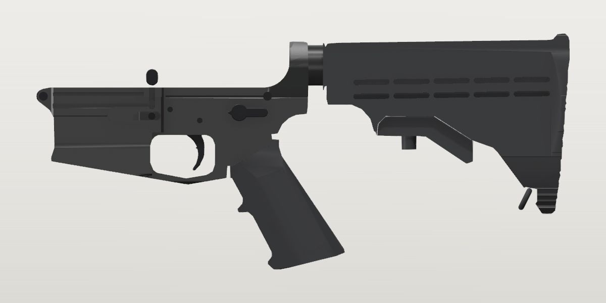
- Weight
- 33.25 oz Confirmedpublished: Aero Precision, the maker, read Oct 2, 2026
- Lowest price
- $350.00 at Aero Precision, read Nov 21, 2026 (Anodized Black)
- Maker's number
- APAR600101
- Colours
- Anodized Black, FDE Cerakote
- Drawn as
- modelled
- Maker's page
- aeroprecisionusa.com
In “22RB on a complete lower”, a build on the start page, as it is.
Its figures
Every figure the site draws and checks it by, with where it came from. Open one for each source's reading, and why one is used where they differ.
Receiver maximum width (Z)1.374 in ± 0.03 in 34.9 mmConflictWorked out: {.panel_right_out} + {.bolt_catch_boss_out}
Photo 1.558 in ± 0.03 in
front view, Aero's studio photo of the stripped M4E1 (the pivot lug above the magwell), harvested
Scale: scale from aero-m4e1-lower.height = 4.079 in (y-extent 542 px → 132.9 px/in). Read by width of the traced outline (tools/trace.py)
The widest point, seen from the front: the side panels at their top, near the deck (the bolt catch's bosses on the left, the fence's panel on the right), not the magwell's mouth (about 1.42 across in this view). Seen from ahead, so read large: the rear view has those panels 1.18 to 1.27 across, and from below (profiles.bottom's photo, ahead of its box) 1.32 to 1.36. (Corrected 2026-10-03: it was taken for the mouth's flare.)
Worked out 1.374 in ± 0.03 in used
{.panel_right_out} + {.bolt_catch_boss_out}, harvested
2026-10-03: the right panel's face and the left bosses' face, both at the deck, each read on two specimens' bottom views at the TDP body's scale.
Photo 1.418 in ± 0.04 in
front view, Aero's studio photo of the stripped M4E1, harvested
Scale: the front lug's slot (std.ar15.front_lug_slot_width, .500 REF): 73 px, 146 px/in. Read by the traced outline's widest, 207 px (1.558 at the height's 132.9 px/in)
The faces read in their own planes on two specimens; the front view at its own standard reads 0.044 wider (its widest row takes in edges seen past the faces), and at the height's scale 10% wider still.
front and faces differ by 0.184 in beyond what each states it is good to.
front and front-own-scale differ by 0.14 in beyond what each states it is good to.
Onboarding checklist: The TDP's body width for a mil-spec forging (std.ar15.lower_body_width); a maker's figure or an end view for anything else. No maker's figure and no end view on file (discovery 2026-10-02). The receiver's body at the pins is a mil-spec upper's mate, so the model uses the TDP's body width there and says so; the M4E1's flared magwell and integral guard are wider and unsourced.
Receiver extension (bore) axis above the takedown pin centre0.877 in ± 0.0015 in 22.3 mmConfirmedWorked out: {std.ar15.bore_axis_y}
Worked out 0.8775 in ± 0.0015 in used
{std.ar15.bore_axis_y}, from the site owner
A lower that takes a standard receiver extension has its thread on the Army drawing's axis (M6). Aero: the M4E1 is "compatible with all mil-spec AR15 parts" (its page, read 2026-10-02), so the standard's hole is its hole.
The published standard; no photo has been read against it yet.
Onboarding checklist: The Army's drawings for a mil-spec lower (std.ar15.bore_axis_y); check it on a pin-framed side photo, allowing for the pins' near ends being nearer the lens.
Magazine seat, X (a seated magazine's frame origin ahead of the takedown pin)3.491 in ± 0.03 in 88.7 mmProvisionalWorked out: {bad-workhorse-lower.magazine_seat_x}
Worked out 3.4915 in ± 0.03 in used
{bad-workhorse-lower.magazine_seat_x}, from the site owner
Where a Black Dog magazine seats in a mil-spec magwell: since 2026-10-03 from the Army drawing's well and catch slot and the user's own magazine (its length, its catch notch), recorded on the Workhorse; the photos of magazines seated in two other rifles are beside it there. The M4E1's magwell is mil-spec inside (Aero: compatible with all mil-spec parts; its "Increased Magwell Flare" is the mouth); a photo of a magazine seated in an M4E1 would make this its own.
The seat belongs to the standard magwell and the magazine's catch notch, not to the receiver's outside; no photo of a magazine seated in an M4E1 is on file.
Onboarding checklist: A pin-framed photo of a magazine seated in it, fitted with its traced outline (trace.py `register`).
Magazine seat, Y (the feed-lip top of a seated magazine)1.003 in ± 0.05 in 25.5 mmProvisionalWorked out: {bad-workhorse-lower.magazine_seat_y}
Worked out 1.003 in ± 0.05 in used
{bad-workhorse-lower.magazine_seat_y}, from the site owner
Where a Black Dog magazine seats in a mil-spec magwell: since 2026-10-03 from the Army drawing's well and catch slot and the user's own magazine (its length, its catch notch), recorded on the Workhorse; the photos of magazines seated in two other rifles are beside it there. The M4E1's magwell is mil-spec inside (Aero: compatible with all mil-spec parts; its "Increased Magwell Flare" is the mouth); a photo of a magazine seated in an M4E1 would make this its own.
The seat belongs to the standard magwell and the magazine's catch notch, not to the receiver's outside; no photo of a magazine seated in an M4E1 is on file.
Onboarding checklist: The same photo. The TDP's magwell (2.553 x 0.898 in inside) bounds any magazine drawn in it.
Grip seat, Y (the underside a grip's flat top bears on, at the takedown pin's X)-1.443 in ± 0.013 in -36.7 mmCorroboratedPhoto: right side, Aero's studio photo of the stripped M4E1 (both pin holes open)
Photo -1.443 in ± 0.013 in used
right side, Aero's studio photo of the stripped M4E1 (both pin holes open), harvested
Scale: rifle frame from reviewed holes takedown (179.5,230.5) r=14px, pivot (937.5,228.5) r=8px = takedown(0.0, 0.0), pivot(6.375, 0.0) (118.9 px/in). Read by silhouette y_min in x [-0.2, 0.08] in frame coordinates; ± from hole-center and edge error
The receiver's underside just behind the step (the tang), where the grip's flat top bears.
Photo -1.444 in ± 0.013 in
left side, Aero's studio photo of the stripped M4E1 (both pin holes open), harvested
Scale: rifle frame from reviewed holes takedown (819.5,267.5) r=15px, pivot (75.5,267.5) r=15px = takedown(0.0, 0.0), pivot(6.375, 0.0) (116.7 px/in). Read by silhouette y_min in x [-0.2, 0.08] in frame coordinates; ± from hole-center and edge error
The receiver's underside just behind the step (the tang), where the grip's flat top bears.
Onboarding: first proposal adopted; the others come from the same method and agree or are flagged.
Onboarding checklist: A pin-framed side photo: the receiver's underside behind the step. Each grip says where its own origin sits from here.
Trigger guard front ear hole, X3.342 in ± 0.007 in 84.9 mmConfirmedWorked out: {std.ar15.trigger_guard_front_x}
Worked out 3.3425 in ± 0.007 in used
{std.ar15.trigger_guard_front_x}, from the site owner
Where a mil-spec guard's front ear hole is. The M4E1's trigger guard is integral (Aero: "Integrated Trigger Guard"), so it has no ear holes; the slot is occupied and nothing is placed by this.
Onboarding checklist: The TDP for a mil-spec lower (std.ar15.*). A lower with an integral trigger guard states where its guard's ears would be, so the fcg and grip anchors still frame it; its guard is drawn with the receiver.
Trigger guard front ear hole, YNo value yetMissingNo source yet
Onboarding checklist: As above. The M4E1's guard is integral (no ear holes), and the standard doesn't give this one: left missing; nothing is placed by it while the guard slot is occupied.
Trigger guard rear ear hole, X1.498 in ± 0.01 in 38.1 mmConfirmedWorked out: {std.ar15.trigger_guard_rear_x}
Worked out 1.4985 in ± 0.01 in used
{std.ar15.trigger_guard_rear_x}, from the site owner
As trigger_guard_front_x: the standard's position; the M4E1's guard is integral.
Onboarding checklist: As above.
Trigger guard rear ear hole, Y-2.18 in ± 0.01 in -55.4 mmConfirmedWorked out: {std.ar15.trigger_guard_rear_y}
Worked out -2.18 in ± 0.01 in used
{std.ar15.trigger_guard_rear_y}, from the site owner
As trigger_guard_front_x: the standard's position; the M4E1's guard is integral.
Onboarding checklist: As above.
Trigger pin hole centre, X1.928 in ± 0.004 in 49 mmConfirmedWorked out: {std.ar15.trigger_pin_x}
Worked out 1.928 in ± 0.004 in used
{std.ar15.trigger_pin_x}, from the site owner
Aero: the M4E1 is "compatible with all mil-spec AR15 parts" (its page, read 2026-10-02), so the standard's hole is its hole.
Onboarding checklist: The TDP (std.ar15.trigger_pin_x); every lower that takes a standard FCG has it there.
Trigger pin hole centre, Y-0.677 in ± 0.015 in -17.2 mmProvisionalPhoto: Aero's studio photo of the stripped M4E1, right side, 1000 x 630
Photo -0.677 in ± 0.015 in used
Aero's studio photo of the stripped M4E1, right side, 1000 x 630, harvested
Scale: pin frame (takedown→pivot pin holes = 6.375 in, 118.8 px/in). Read by Hough circle on the open trigger pin hole, (403.8, 311.4) px, r 8.6 px (0.145 in: the .154 hole); the takedown hole's centre at (179.4, 231.0). Its x reads 1.889, 0.04 behind the standard's 1.928, as the Workhorse's photos did (the pins' near ends nearer the lens).
The Workhorse's photos read -0.678 and -0.689 for the same standard hole.
Onboarding checklist: The TDP; checked on a pin-framed photo.
The trigger's face ahead of the takedown pin (a complete lower: its trigger, at rest)1.964 in ± 0.015 in 49.9 mmConflictPhoto: Aero's studio photo of the complete lower, right side, 1000 x 630
Photo 2.06 in ± 0.06 in
Aero's studio photo of the complete lower, right side, 1000 x 630, harvested
Scale: pin frame (takedown→pivot pin heads = 6.375 in, 60.1 px/in). Read by The trigger's blade on the integral guard's window feature polygon (profiles.complete.features.guard_window, tools/trace.py): its front edge runs from (2.18, -1.21) down through (2.02, -1.43), (1.97, -1.63), (2.02, -1.91) to the tip at (2.13, -2.10). The face where a finger lands, mid-blade: 2.06, and the ± covers the edge's lean.
A mil-spec trigger at rest (Aero's lower parts kit). The LaRue MBT-2S on the Workhorse sits 2.06 ahead of the pin too (its pin 1.928 + 0.129).
Photo 1.964 in ± 0.015 in used
Aero's studio photo of the complete lower, right side, 1000 x 630, harvested
Scale: pin frame (takedown→pivot pin heads = 6.375 in, 60.2 px/in, the frame turned 0.30° to them). Read by The blade's front edge where it stands black against the guard's white window, at half level, row by row from y -1.25 to -2.10 (every 0.05): 2.131 at the top, its deepest 1.964 at y -1.65 to -1.70, 2.125 at -2.10. The deepest point is the face. ± is a pixel (0.017) on a black-on-white edge read to a fraction of one, and the frame's scale.
Read again on 2026-10-03, when the Army drawing's trigger (profiles.trigger) turned to this photo had its face's deepest point at 1.978, y -1.73: 0.08 behind the first reading.
Length of pull runs to the face where the finger lies, the deepest point of the blade's curve. The first reading (2.06 ± 0.06) is the middle of the edge's span from its top to its tip, which is no point on it; the drawing's outline at the fitted rest angle agrees with the edge (1.978).
complete and complete_edge differ by 0.096 in beyond what each states it is good to.
Onboarding checklist: A pin-framed side photo of the complete lower: the front of the trigger's shoe where a finger lands. Length of pull is read from here.
The trigger at rest: how far it is turned about its pin from the Army drawing's side elevation (positive turns the blade forward)-1° ± 0.8°ProvisionalPhoto: Aero's studio photo of the complete lower, right side, 1000 x 630
Photo -1 deg ± 0.8 deg used
Aero's studio photo of the complete lower, right side, 1000 x 630, harvested
Scale: pin frame (takedown→pivot pin heads = 6.375 in, 60.2 px/in). Read by The traced outline (profiles.trigger, from drawing 8448592) turned about the trigger pin to the blade's front edge and tip read on the photo (trigger_face_x's five points): best at -1.0 deg, rms 0.007 in; one pixel (0.017 in) at the blade, 1.4 in from the pin, is 0.7 deg.
The drawing's elevation has the trigger's tail level; at rest in the lower the trigger sits against the disconnector and hammer, which no drawing on file shows.
The stock's butt behind the takedown pin, at the position it is drawn at (a complete lower)8.601 in ± 0.054 in 218.5 mmCorroboratedPhoto: right side, Aero's studio photo of the complete lower APAR600101 (pin heads in place; the stock partly extended)
Photo 8.601 in ± 0.054 in used
right side, Aero's studio photo of the complete lower APAR600101 (pin heads in place; the stock partly extended), harvested
Scale: rifle frame from reviewed holes takedown (560.5,218.5) r=14px, pivot (944.5,216.5) r=10px = takedown(0.0, 0.0), pivot(6.375, 0.0) (60.2 px/in). Read by silhouette x_min in frame coordinates (negated); ± from hole-center and edge error
The stock's butt (its rearmost point), at the position Aero's photo shows: partly extended.
Photo 8.611 in ± 0.054 in
left side, Aero's studio photo of the complete lower APAR600101, harvested
Scale: rifle frame from reviewed holes takedown (438.5,222.5) r=7px, pivot (55.5,221.5) r=5px = takedown(0.0, 0.0), pivot(6.375, 0.0) (60.1 px/in). Read by silhouette x_min in frame coordinates (negated); ± from hole-center and edge error
The stock's butt (its rearmost point), at the position Aero's photo shows: partly extended.
Onboarding: first proposal adopted; the others come from the same method and agree or are flagged.
Onboarding checklist: A pin-framed side photo of the complete lower with its stock collapsed (say which position); the stock maker's lengths of pull are a check only (M6).
Overall height: the tower ring's top to the lowest point (the end views are scaled by it)4.079 in ± 0.03 in 103.6 mmProvisionalPhoto: right side, Aero's studio photo of the stripped M4E1, pin-framed by its open holes
Photo 4.079 in ± 0.03 in used
right side, Aero's studio photo of the stripped M4E1, pin-framed by its open holes, harvested
Scale: frame from the reviewed holes takedown (179.5,230.5) r=14px, pivot (937.5,228.5) r=8px (118.9 px/in, rms 0.000 in over 2 points). Read by height of the traced outline (tools/trace.py)
The tower ring's top to the lowest point: what the end views are scaled by.
From the pin-framed photos (tools/onboard.py measure, tools/trace.py).
The buffer tower's ring, across (the end view; the standard's is 1.392)1.351 in ± 0.03 in 34.3 mmConflictPhoto: rear view, Aero's studio photo of the stripped M4E1 (the tower ring above, the magwell below)
Photo 1.351 in ± 0.03 in used
rear view, Aero's studio photo of the stripped M4E1 (the tower ring above, the magwell below), harvested
Scale: scale from aero-m4e1-lower.height = 4.079 in (y-extent 544 px → 133.4 px/in). Read by median row width in y [-0.9, -0.5] (1.290–1.365) of the traced outline (tools/trace.py)
The buffer tower's ring, across; the standard's is 1.392.
Photo 1.275 in ± 0.03 in
rear view, Aero's studio photo of the stripped M4E1 in FDE Cerakote (APAR600002C), harvested
Scale: scale from aero-m4e1-lower.height = 4.079 in (y-extent 544 px → 133.4 px/in). Read by median row width in y [-0.9, -0.5] (1.200–1.290) of the traced outline (tools/trace.py)
The ring across, on the FDE specimen's photo in the black one's pose: the same 544 px tall, the ring 10 px narrower.
The black photo, the rear profile's. The bottom view (profiles.bottom) is scaled by this: at 1.351 its length from the rear face to where the sides rise into the magazine well's panels is 3.997 (the right photo's fence slope from rear_face_x: 4.014; from the TDP's rear face: 3.999) and its body 0.894 (the TDP's 0.88); at 1.275 they would be 3.77 and 0.84. The two rear photos, both scaled by the side's height, are 6% apart: how far a height-scaled end view's widths hold. The ring has flats (the rear view's sides run straight over 0.19 in; from below its top is a flat 0.58 wide), so the TDP's round 1.392 isn't its width across.
rear and rear_fde differ by 0.076 in beyond what each states it is good to.
From the pin-framed photos (tools/onboard.py measure, tools/trace.py).
Rear of the buffer-tower ring behind the takedown pin1.155 in ± 0.013 in 29.3 mmCorroboratedPhoto: right side, Aero's studio photo of the stripped M4E1 (both pin holes open)
Photo 1.155 in ± 0.013 in used
right side, Aero's studio photo of the stripped M4E1 (both pin holes open), harvested
Scale: rifle frame from reviewed holes takedown (179.5,230.5) r=14px, pivot (937.5,228.5) r=8px = takedown(0.0, 0.0), pivot(6.375, 0.0) (118.9 px/in). Read by silhouette x_min in frame coordinates (negated); ± from hole-center and edge error
Rearmost point: the buffer-tower ring.
Photo 1.135 in ± 0.013 in
left side, Aero's studio photo of the stripped M4E1 (both pin holes open), harvested
Scale: rifle frame from reviewed holes takedown (819.5,267.5) r=15px, pivot (75.5,267.5) r=15px = takedown(0.0, 0.0), pivot(6.375, 0.0) (116.7 px/in). Read by silhouette x_min in frame coordinates (negated); ± from hole-center and edge error
Rearmost point: the buffer-tower ring.
Onboarding: first proposal adopted; the others come from the same method and agree or are flagged.
From the pin-framed photos (tools/onboard.py measure, tools/trace.py).
Front of the pivot-pin lug ahead of the takedown pin6.547 in ± 0.022 in 166.3 mmConflictPhoto: right side, Aero's studio photo of the stripped M4E1 (both pin holes open)
Photo 6.547 in ± 0.022 in used
right side, Aero's studio photo of the stripped M4E1 (both pin holes open), harvested
Scale: rifle frame from reviewed holes takedown (179.5,230.5) r=14px, pivot (937.5,228.5) r=8px = takedown(0.0, 0.0), pivot(6.375, 0.0) (118.9 px/in). Read by silhouette x_max in frame coordinates; ± from hole-center and edge error
Front of the pivot-pin lug.
Photo 6.645 in ± 0.023 in
left side, Aero's studio photo of the stripped M4E1 (both pin holes open), harvested
Scale: rifle frame from reviewed holes takedown (819.5,267.5) r=15px, pivot (75.5,267.5) r=15px = takedown(0.0, 0.0), pivot(6.375, 0.0) (116.7 px/in). Read by silhouette x_max in frame coordinates; ± from hole-center and edge error
Front of the pivot-pin lug.
The right photo; the left reads the lug 0.10 further forward (perspective at the front end, as the Workhorse's photos did), and the complete lower's right photo agrees with the right (6.574).
right and left differ by 0.098 in beyond what each states it is good to.
From the pin-framed photos (tools/onboard.py measure, tools/trace.py).
Top of the buffer-tower ring above the pin line1.554 in ± 0.013 in 39.5 mmCorroboratedPhoto: right side, Aero's studio photo of the stripped M4E1 (both pin holes open)
Photo 1.554 in ± 0.013 in used
right side, Aero's studio photo of the stripped M4E1 (both pin holes open), harvested
Scale: rifle frame from reviewed holes takedown (179.5,230.5) r=14px, pivot (937.5,228.5) r=8px = takedown(0.0, 0.0), pivot(6.375, 0.0) (118.9 px/in). Read by silhouette y_max in frame coordinates; ± from hole-center and edge error
Top of the buffer-tower ring.
Photo 1.572 in ± 0.014 in
left side, Aero's studio photo of the stripped M4E1 (both pin holes open), harvested
Scale: rifle frame from reviewed holes takedown (819.5,267.5) r=15px, pivot (75.5,267.5) r=15px = takedown(0.0, 0.0), pivot(6.375, 0.0) (116.7 px/in). Read by silhouette y_max in frame coordinates; ± from hole-center and edge error
Top of the buffer-tower ring.
Onboarding: first proposal adopted; the others come from the same method and agree or are flagged.
From the pin-framed photos (tools/onboard.py measure, tools/trace.py).
Receiver top deck above the pin line0.247 in ± 0.013 in 6.3 mmCorroboratedPhoto: right side, Aero's studio photo of the stripped M4E1 (both pin holes open)
Photo 0.247 in ± 0.013 in used
right side, Aero's studio photo of the stripped M4E1 (both pin holes open), harvested
Scale: rifle frame from reviewed holes takedown (179.5,230.5) r=14px, pivot (937.5,228.5) r=8px = takedown(0.0, 0.0), pivot(6.375, 0.0) (118.9 px/in). Read by silhouette y_max in x [0.6, 5.8] in frame coordinates; ± from hole-center and edge error
Receiver top edge between the tower and the pivot lug (where the upper sits).
Photo 0.253 in ± 0.013 in
left side, Aero's studio photo of the stripped M4E1 (both pin holes open), harvested
Scale: rifle frame from reviewed holes takedown (819.5,267.5) r=15px, pivot (75.5,267.5) r=15px = takedown(0.0, 0.0), pivot(6.375, 0.0) (116.7 px/in). Read by silhouette y_max in x [0.6, 5.8] in frame coordinates; ± from hole-center and edge error
Receiver top edge between the tower and the pivot lug (where the upper sits).
Onboarding: first proposal adopted; the others come from the same method and agree or are flagged.
From the pin-framed photos (tools/onboard.py measure, tools/trace.py).
Lowest point below the pin line (the integral guard or the magwell front)2.508 in ± 0.014 in 63.7 mmCorroboratedPhoto: right side, Aero's studio photo of the stripped M4E1 (both pin holes open)
Photo 2.508 in ± 0.014 in used
right side, Aero's studio photo of the stripped M4E1 (both pin holes open), harvested
Scale: rifle frame from reviewed holes takedown (179.5,230.5) r=14px, pivot (937.5,228.5) r=8px = takedown(0.0, 0.0), pivot(6.375, 0.0) (118.9 px/in). Read by silhouette y_min in frame coordinates (negated); ± from hole-center and edge error
Lowest point: the integral trigger guard's bow or the magwell's front.
Photo 2.523 in ± 0.015 in
left side, Aero's studio photo of the stripped M4E1 (both pin holes open), harvested
Scale: rifle frame from reviewed holes takedown (819.5,267.5) r=15px, pivot (75.5,267.5) r=15px = takedown(0.0, 0.0), pivot(6.375, 0.0) (116.7 px/in). Read by silhouette y_min in frame coordinates (negated); ± from hole-center and edge error
Lowest point: the integral trigger guard's bow or the magwell's front.
Onboarding: first proposal adopted; the others come from the same method and agree or are flagged.
From the pin-framed photos (tools/onboard.py measure, tools/trace.py).
Magwell front face, X6.156 in ± 0.021 in 156.4 mmConflictPhoto: right side, Aero's studio photo of the stripped M4E1 (both pin holes open)
Photo 6.156 in ± 0.021 in used
right side, Aero's studio photo of the stripped M4E1 (both pin holes open), harvested
Scale: rifle frame from reviewed holes takedown (179.5,230.5) r=14px, pivot (937.5,228.5) r=8px = takedown(0.0, 0.0), pivot(6.375, 0.0) (118.9 px/in). Read by silhouette x_max in x [3.0, 7.0] in y [-1.95, -1.3] in frame coordinates; ± from hole-center and edge error
Front face of the magwell.
Photo 6.268 in ± 0.022 in
left side, Aero's studio photo of the stripped M4E1 (both pin holes open), harvested
Scale: rifle frame from reviewed holes takedown (819.5,267.5) r=15px, pivot (75.5,267.5) r=15px = takedown(0.0, 0.0), pivot(6.375, 0.0) (116.7 px/in). Read by silhouette x_max in x [3.0, 7.0] in y [-1.95, -1.3] in frame coordinates; ± from hole-center and edge error
Front face of the magwell.
Onboarding: first proposal adopted; the others come from the same method and agree or are flagged.
right and left differ by 0.112 in beyond what each states it is good to.
From the pin-framed photos (tools/onboard.py measure, tools/trace.py).
Receiver rear face below the tower ring, X-1.14 in ± 0.013 in -29 mmCorroboratedPhoto: right side, Aero's studio photo of the stripped M4E1 (both pin holes open)
Photo -1.14 in ± 0.013 in used
right side, Aero's studio photo of the stripped M4E1 (both pin holes open), harvested
Scale: rifle frame from reviewed holes takedown (179.5,230.5) r=14px, pivot (937.5,228.5) r=8px = takedown(0.0, 0.0), pivot(6.375, 0.0) (118.9 px/in). Read by silhouette x_min in y [-1.0, 0.0] in frame coordinates; ± from hole-center and edge error
Rear face of the receiver below the buffer-tower ring.
Photo -1.118 in ± 0.013 in
left side, Aero's studio photo of the stripped M4E1 (both pin holes open), harvested
Scale: rifle frame from reviewed holes takedown (819.5,267.5) r=15px, pivot (75.5,267.5) r=15px = takedown(0.0, 0.0), pivot(6.375, 0.0) (116.7 px/in). Read by silhouette x_min in y [-1.0, 0.0] in frame coordinates; ± from hole-center and edge error
Rear face of the receiver below the buffer-tower ring.
Onboarding: first proposal adopted; the others come from the same method and agree or are flagged.
From the pin-framed photos (tools/onboard.py measure, tools/trace.py).
The A2 grip's lowest point below the pin line (the complete lower)4.93 in ± 0.031 in 125.2 mmProvisionalPhoto: right side, Aero's studio photo of the complete lower APAR600101, pin-framed by its pin heads
Photo 4.93 in ± 0.031 in used
right side, Aero's studio photo of the complete lower APAR600101, pin-framed by its pin heads, harvested
Scale: frame from the reviewed holes takedown (560.5,218.5) r=14px, pivot (944.5,216.5) r=10px (60.2 px/in, rms 0.000 in over 2 points). Read by −y_min in x [-2.3, 0.2] of the traced outline (tools/trace.py)
The A2 grip's lowest point, on the complete lower's silhouette (the grip hangs behind the takedown pin).
From the complete lower's traced silhouette (tools/trace.py); the measure stage's reading was the stock's latch, not the grip.
The A2 grip's width over its knurl (Z)1.27 in ± 0.02 in 32.3 mmConfirmedStandard: US Army TDP drawing 9349127 (Grip, Pistol), rev J, sheet 1 of 1 (filmed in two frames: frame 1 of 2, the M16 package's PDF page 33), the bottom view: the grip seen along its axis, below and behind the side view
Standard “1.270 APPROX OVER KNURL” used
US Army TDP drawing 9349127 (Grip, Pistol), rev J, sheet 1 of 1 (filmed in two frames: frame 1 of 2, the M16 package's PDF page 33), the bottom view: the grip seen along its axis, below and behind the side view, from the site owner
The drawing's "APPROX" taken as ± 0.02. Read between the bottom view's two extension lines, which are tangent to its outline's sides (346.6 px apart on the 600 dpi scan between the lines' middles; the traced outline, at its strokes' middle, is 345 across). First cited (2026-10-02) as Section A-A: that is a partial section through the backstrap's serrations at the grip's lower rear, with no width on it. Aero's page says "A2 Grip - Black": the mil-spec pattern, which the drawing dimensions; the checkering's pitch (14) and the slot are there too.
The A2 grip is the TDP's pistol grip (9349127). The width over the knurl is the widest the grip is; its top, where it bears on the receiver, is .885 (grip_body_width). The drawing says DO NOT SCALE: its interface dimensions are drawn 5 to 7% off (1.275 and 1.390 read 258 and 263 px/in), while its exterior views agree with Aero's photo within 2% (the side view registered on profiles.complete at 277 px/in, rms 0.013 in; the bottom view, scaled by this width, at 272 px/in, and by the photo's depth square to the axis at 272.5). The bottom view's .39 ± .01 (its centre line to the front end's theoretical corner) lands at 0.38 in the traced section. Its Section D-D says the exterior contour is "per sample furnished by the contractor and approved by the Government technical activity".
The A2 grip's top, across (Z): the block that bears on the receiver (the slot along it is .380 + .005 wide)0.885 in ± 0.015 in 22.5 mmConfirmedStandard: US Army TDP drawing 9349127 (Grip, Pistol), rev J, sheet 1, frame 1 of 2 (PDF page 33), the top view
Standard “.885 ± .015” used
US Army TDP drawing 9349127 (Grip, Pistol), rev J, sheet 1, frame 1 of 2 (PDF page 33), the top view, from the site owner
Between the top view's extension lines from the block's two long edges (datum -A- is its centre plane; the slot in it is .380 + .005 wide). The front view shows the block this wide for about the top quarter of the grip's height before the body widens to the knurl. As drawn it reads 0.85 (top view) and 0.84 (front view) at the scale the exterior views share: drawn 4 to 5% narrow. This entry first held Section C-C's ".820 ± .01" (2026-10-02), read as a width at the tang: Section C-C is the mid-plane section (its cut line is the front view's centre line), so nothing on it spans Z; the .820 runs along the grip's axis, between two lines square to it below the slot.
The A2 grip's axis from its top face: the screw bore, along which the drawing's bottom view looks60° ± 1°ConfirmedStandard: US Army TDP drawing 9349127 (Grip, Pistol), rev J, sheet 1: Section C-C (frame 2 of 2, PDF page 32) and the side view (frame 1, PDF page 33)
Standard “60° (basic) between datum -E- (the top face) and the bore, Section C-C; 30° ± 1° between the top face and the lines square to the axis, the side view” used
US Army TDP drawing 9349127 (Grip, Pistol), rev J, sheet 1: Section C-C (frame 2 of 2, PDF page 32) and the side view (frame 1, PDF page 33), from the site owner
The ± is the side view's ± 1° on the 30°. As scanned, the side view's 30° lines lie 29.4° and 29.6° below its top face, and the bottom view's long axis (its 1.270's extension lines) 29.4°: the view is drawn square to this axis.
The A2 grip's top face against the bore line, in the rifle frame (+: rising toward the muzzle)1.7° ± 0.6°ProvisionalPhoto: right side, Aero's studio photo of the complete lower APAR600101, traced as profiles.complete) and be585e351439 (US Army TDP drawing 9349127, frame 1 of 2: its side view
Photo 1.7 deg ± 0.6 deg used
right side, Aero's studio photo of the complete lower APAR600101, traced as profiles.complete) and be585e351439 (US Army TDP drawing 9349127, frame 1 of 2: its side view, from the site owner
Scale: the complete lower's pin frame (std.ar15.pin_spacing); the drawing's scale is fitted with the rotation. Read by The drawing's side view, filled and its lines opened away, registered by a similarity (ICP) on the traced outline below the receiver (its top 0.3 in left out, where the receiver hides the grip in the photo): 277.3 px/in, rotation +1.28° onto a top face that lies at +0.38° on the scan, rms 0.013 in over 2794 points. The ± is the spread of the rotation over parts of the outline (the rear half alone +0.9°, the front half +2.2°). Scratch: a working script, register_var.py.
The grip's top face, where the drawing levels it, sits 1.7° nose-up on Aero's lower. Read off one photo of one lower; with grip_axis_angle it sets grip_rake.
The A2 grip's axis from the vertical in the rifle frame (its bottom further back): the side outline turns by this to stand the axis up28.3° ± 1.2°ProvisionalWorked out: 90 - {.grip_axis_angle} - {.grip_top_slope}
Worked out 28.3 deg ± 1.2 deg used
90 - {.grip_axis_angle} - {.grip_top_slope}, from the site owner
The bottom view (profiles.grip_section) is a plan in the frame this angle stands up. With the top face taken as level it would be 30°, and the photo's depth along the section (grip_depth) 2.095 against the bottom view's 2.159.
The A2 grip's depth square to its axis: its side outline's whole extent along the direction grip_rake below the bore line, toward the muzzle2.153 in ± 0.05 in 54.7 mmProvisionalPhoto: right side, Aero's studio photo of the complete lower APAR600101, pin-framed by its pin heads
Photo 2.153 in ± 0.05 in used
right side, Aero's studio photo of the complete lower APAR600101, pin-framed by its pin heads, harvested
Scale: the pin frame of the complete lower's traced outline (profiles.complete, std.ar15.pin_spacing). Read by profiles.complete below y -2.5 between x -2.5 and 1.0 (the grip below the receiver, behind the guard) projected on the direction 28.3° (grip_rake) below the bore line: from the bottom-rear corner (-2.181, -4.347) to the finger swell (0.846, -3.267). The ± covers the outline's 0.02 and grip_rake's ± 1.2° (0.036 in a degree here); the receiver hides nothing that reaches further along it (the drawing registered on the photo puts the top block's front at 2.08).
What the bottom view (profiles.grip_section) is scaled by along its length, so that its extent along x' is the side outline's and a visual hull of the two meets at both ends. The bottom view scaled by grip_width across gives 2.157 for its length: within 0.2%.
The A2 grip's top face (where it bears on the receiver), its height at the takedown pin's X in the part frame; it rises grip_top_slope toward the muzzle-1.221 in ± 0.05 in -31 mmProvisionalPhoto: right side, Aero's studio photo of the complete lower APAR600101, traced as profiles.complete) and be585e351439 (US Army TDP drawing 9349127, frame 1 of 2: its side view
Photo -1.221 in ± 0.05 in used
right side, Aero's studio photo of the complete lower APAR600101, traced as profiles.complete) and be585e351439 (US Army TDP drawing 9349127, frame 1 of 2: its side view, from the site owner
Scale: the complete lower's pin frame (std.ar15.pin_spacing); the drawing's scale is fitted with the rotation. Read by The registration grip_top_slope is read from (the drawing's side view on the traced outline below the receiver, ICP, 277.3 px/in, rms 0.013 in) carries the side view's top line (fitted at (3425.0, 2413.1) px, +0.38° on the scan) into the part frame: y −1.221 at x 0, −1.230 at the grip's rear-top corner (x −0.34) and −1.190 at the top block's front (x 1.07). The ± is the spread over parts of the outline (−1.218 to −1.245; the rear half alone, fitted at 282 px/in, −1.282): the face is extrapolated from 0.3 in below it, where the receiver stops hiding the grip.
Where the grip's front view (profiles.grip_front) is hung: its top is this face. 0.22 above grip_seat_y (−1.443), which is the receiver's underside behind the step at the pin's X, not the face a grip bears on: the receiver's lug stands into the grip's slot below it.
The A2 grip's height: its top face to its lowest point3.709 in ± 0.06 in 94.2 mmProvisionalWorked out: {.grip_bottom_y} + {.grip_top_y}
Worked out 3.709 in ± 0.06 in used
{.grip_bottom_y} + {.grip_top_y}, from the site owner
Taken square to the bore line; square to the top face (1.7° off) the lowest point is 0.007 lower, inside the ±. The drawing's front view is drawn this tall at the scale its side view takes on Aero's photo (1026 px at 277 px/in: 3.70); scaled by its block's stated .885 it is 3.90 (profiles.grip_front's check).
The M4 stock's width (Z), its body1.443 in ± 0.02 in 36.7 mmCorroboratedPhoto: US D620,067 S, the Army's design patent for an M4-pattern buttstock, sheet 3, FIG. 3 top plan, 300 dpi
Photo 1.443 in ± 0.02 in used
US D620,067 S, the Army's design patent for an M4-pattern buttstock, sheet 3, FIG. 3 top plan, 300 dpi, harvested
Scale: the receiver extension in the same figure, 191 px across, as the standard's mil-spec OD (std.receiver_extension.milspec_od, 1.148 in): 166.4 px/in. Read by the body's width in the plan view, 240 px (± 1) all along it from the stock's front to the butt's flare
Published “Width 1.4 in (35.4 mm)”
Leapers, UTG PRO 6-Position Mil-spec Stock (RBU6BM), its dimensions table: a clone of the M4 pattern, not Aero's stock, the maker, read Oct 2, 2026 the page, harvested Oct 2, 2026
Published “There are various manufacturers of this type of stock out there, but the outside width of the stock should be 1.4" for best fit.”
Hurley Welding, Cheek Riser for M4/A1 'Waffle' Stock: the width of the USGI-pattern stocks it fits, a seller, read Oct 2, 2026 the page, harvested Oct 2, 2026
Measured in an orthographic drawing against a standard in the same figure; the two stated figures, to a tenth, agree with it.
The body's, which a cheek riser fits over; the butt flares wider (stock_butt_width). Aero's page for the stock it ships (M4 Sliding Stock, APRH100033C) states 7.2 oz and no dimensions (read 2026-10-02); a distributor's '2 in' for it is behind a robots.txt that refuses us. The two figures and the patent are for the M4 pattern (a clone's table, a riser maker's fit, the Army's design): Aero's stock is that pattern, with slots in its sides where the patent's has pockets.
The M4 stock's width at its butt (Z), where it flares1.707 in ± 0.02 in 43.4 mmProvisionalPhoto: US D620,067 S, the Army's design patent for an M4-pattern buttstock, sheet 3, FIG. 3 top plan, 300 dpi
Photo 1.707 in ± 0.02 in used
US D620,067 S, the Army's design patent for an M4-pattern buttstock, sheet 3, FIG. 3 top plan, 300 dpi, harvested
Scale: the receiver extension in the same figure, 191 px across, as the standard's mil-spec OD (std.receiver_extension.milspec_od, 1.148 in): 166.4 px/in. Read by the butt's width in the plan view at its widest, 284 px (± 1), 0.18 to 0.27 in ahead of its rear face
The patent's rear elevation (FIG. 6), scaled by the stock's height alone, reads 1.74 at its widest: within 2%.
The M4 stock's butt flare, how far ahead of the rear face it begins0.535 in ± 0.03 in 13.6 mmProvisionalPhoto: US D620,067 S, the Army's design patent for an M4-pattern buttstock, sheet 3, FIG. 3 top plan, 300 dpi
Photo 0.535 in ± 0.03 in used
US D620,067 S, the Army's design patent for an M4-pattern buttstock, sheet 3, FIG. 3 top plan, 300 dpi, harvested
Scale: the receiver extension in the same figure, 191 px across, as the standard's mil-spec OD (std.receiver_extension.milspec_od, 1.148 in): 166.4 px/in. Read by the last column with ink (the rear face) to the first column wider than the body, 89 px
From the butt's rear face forward it stays at its full width 0.23 in, then narrows to the body's by this distance.
The M4 stock's butt, how far ahead of the rear face it stays at full width0.234 in ± 0.03 in 5.9 mmProvisionalPhoto: US D620,067 S, the Army's design patent for an M4-pattern buttstock, sheet 3, FIG. 3 top plan, 300 dpi
Photo 0.234 in ± 0.03 in used
US D620,067 S, the Army's design patent for an M4-pattern buttstock, sheet 3, FIG. 3 top plan, 300 dpi, harvested
Scale: the receiver extension in the same figure, 191 px across, as the standard's mil-spec OD (std.receiver_extension.milspec_od, 1.148 in): 166.4 px/in. Read by the rear face to where the width drops from 284 px, 39 px
The M4 stock's height, its top to its toe5.179 in ± 0.03 in 131.5 mmCorroboratedPhoto: right side, Aero's studio photo of the complete lower APAR600101
Photo 5.179 in ± 0.03 in used
right side, Aero's studio photo of the complete lower APAR600101, harvested
Scale: the pin frame of the complete lower's traced outline (std.ar15.pin_spacing). Read by the traced outline's height inside the stock's box (profiles.complete, features.stock): 1.787 above the pin line to 3.392 below
Published “Height 5.1 in (130 mm)”
Leapers, UTG PRO 6-Position Mil-spec Stock (RBU6BM): a clone of the M4 pattern, the maker, read Oct 2, 2026 the page, harvested Oct 2, 2026
Aero's own stock, in the photo the rest of the lower is traced from; the clone's figure is to a tenth.
The M4 stock's weight on its own (Aero's M4 Sliding Stock)7.2 ozConfirmedPublished: Aero Precision, the maker, read Oct 2, 2026
Published 7.2 oz used
Aero Precision, the maker, read Oct 2, 2026 the page, harvested Oct 2, 2026
"Weight(s) 7.2 oz" on Aero's page for the stock sold on its own (APRH100033C); the complete lower's page names it "M4 Stock - Black". For the centre of mass (mass.lumps), not the build's weight: the complete lower's 33.25 oz counts it.
The receiver's rear below the tower ring, across (Z)1.04 in ± 0.03 in 26.4 mmProvisionalPhoto: rear view, Aero's studio photo of the stripped M4E1 (the tower ring above, the magwell below)
Photo 1.04 in ± 0.03 in used
rear view, Aero's studio photo of the stripped M4E1 (the tower ring above, the magwell below), harvested
Scale: scale from aero-m4e1-lower.height = 4.079 in (y-extent 544 px → 133.4 px/in). Read by median row width in y [-2.0, -1.3] (0.855–1.282) of the traced outline (tools/trace.py)
The rear view's outline at those heights, across: the bolt catch's bosses and the right panel, which stand 3 to 4.5 in ahead of the rear face, with the takedown lug's ears between them. Not the rear end's own width (the model review, 2026-10-05): the near end there is the body's, 0.84 in across on this photo, and the outline's waist under the ring is 0.855; the model holds the receiver behind the takedown pin to std.ar15.lower_body_width below that waist.
From the rear view (tools/trace.py).
The M4 stock's top above the pin line (the complete lower)1.787 in ± 0.03 in 45.4 mmProvisionalPhoto: right side, Aero's studio photo of the complete lower APAR600101, pin-framed by its pin heads
Photo 1.787 in ± 0.03 in used
right side, Aero's studio photo of the complete lower APAR600101, pin-framed by its pin heads, harvested
Scale: frame from the reviewed holes takedown (560.5,218.5) r=14px, pivot (944.5,216.5) r=10px (60.2 px/in, rms 0.000 in over 2 points). Read by y_max in x [-8.6, -1.2] of the traced outline (tools/trace.py)
The M4 stock's top, above the pin line.
From the complete lower's traced silhouette.
The carbine buffer kit's weight on its own (Aero's AR15/M4 Carbine Buffer Kit, No Stock)9.8 ozConfirmedPublished: Aero Precision, the maker, read Oct 2, 2026
Published 9.8 oz used
Aero Precision, the maker, read Oct 2, 2026 the page, harvested Oct 2, 2026
"Weight(s) 9.8 oz" on Aero's page for the kit sold on its own: the receiver extension, carbine buffer, spring, end plate and castle nut, which the complete lower's page lists as "Carbine Receiver Extension" and "AR15 Carbine Buffer and Spring". For the centre of mass (mass.lumps), not the build's weight.
Aero's extension alone is 3.8 oz and its carbine buffer 3.0 (their own pages, read 2026-10-02); the spring, end plate and nut make up the rest of the 9.8.
The carbine receiver extension's length behind the receiver's rear face7.25 in ± 0.1 in 184.1 mmCorroboratedWorked out: {bcm-receiver-extension.tube_length}
Worked out 7.25 in ± 0.1 in used
{bcm-receiver-extension.tube_length}, from the site owner
A mil-spec carbine extension's length as two generic sources give it (recorded on the BCM kit: 7.25); Aero's page for its extension states no length. Places the buffer kit's weight for the centre of mass; nothing is drawn to it (the stock covers the tube).
The only figure on file; Aero states none. Provisional, like the BCM kit's.
The right side panel's face, from the centre plane0.664 in ± 0.02 in 16.9 mmCorroboratedPhoto: Aero's FDE gallery: the stripped receiver from below
Photo 0.664 in ± 0.02 in used
Aero's FDE gallery: the stripped receiver from below, harvested
Scale: the body's width behind the panels, 92.9 px on rows 380-420, as std.ar15.lower_body_width (0.880): 105.6 px/in. Read by the 50% edge on rows 540-580 at u 566.9, against the body's centre at u 496.8: 70.1 px
Photo 0.674 in ± 0.02 in
AT3 Tactical's gallery: the black stripped receiver from below, 1200 px, harvested
Scale: the body's width behind the panels, 137.8-138.1 px, as std.ar15.lower_body_width (0.880): 156.9 px/in. Read by u 719.6 against the centre 613.8 (carried forward: the photo is turned 0.66°); across both panels 1.331, the FDE one's 1.330
Photo 0.674 in ± 0.03 in
Aero's stripped M4E1 from the front, 1000 x 631, harvested
Scale: the front lug's slot (std.ar15.front_lug_slot_width, .500 REF): 73 px on row 250, 146 px/in. Read by u 401.6 on rows 180-360, from the centre at u 500
Two specimens, each scaled in its own plane by the TDP's body, agree; the FDE view's centre is the better defined.
It stands 0.12 in proud of the drawing's fence (0.549): Aero's own forging. The end views can't give it: the rear view's far features are shifted 0.09 sideways, and the front view's height scale reads widths 10% large.
The right side panel's face, where it begins (its ramp's foot 0.17 behind)3.09 in ± 0.04 in 78.5 mmProvisionalPhoto: Aero's stripped M4E1, right side, pin-framed
Photo 3.09 in ± 0.04 in used
Aero's stripped M4E1, right side, pin-framed, harvested
Scale: its open pin holes: 118.9 px/in; its x reads about 0.04 short (the trigger hole 1.889 against 1.928). Read by the panel's lit edge, corrected by the photo's +0.04; its ramp from 2.92; the FDE bottom view's ramp, once placed, 2.94 to 3.20
The right side panel's ramp up from the body, its length along x0.17 in ± 0.04 in 4.3 mmProvisionalPhoto: Aero's stripped M4E1, right side, pin-framed
Photo 0.17 in ± 0.04 in used
Aero's stripped M4E1, right side, pin-framed, harvested
Scale: its open pin holes: 118.9 px/in; its x reads about 0.04 short (the trigger hole 1.889 against 1.928). Read by from the ramp's foot (2.92) to the face (3.09)
The right side panel's lower edge, Y (below it the well's wall steps in)-1.03 in ± 0.04 in -26.2 mmProvisionalPhoto: Aero's stripped M4E1 from the front, 1000 x 631
Photo -1.03 in ± 0.04 in used
Aero's stripped M4E1 from the front, 1000 x 631, harvested
Scale: the front lug's slot (std.ar15.front_lug_slot_width, .500 REF): 73 px on row 250, 146 px/in. Read by the step in the right side's outline below the deck (v 175 = Y 0.245)
The raised block round the magazine catch on the right side, where its face ends at the front, X3.64 in ± 0.02 in 92.5 mmCorroboratedWorked out: {aero-m4e1-stripped-lower.catch_block_front_x}
Worked out 3.64 in ± 0.02 in used
{aero-m4e1-stripped-lower.catch_block_front_x}, harvested
By reference: the same receiver (Aero's page for this complete lower: "Includes: M4E1 Stripped Lower Receiver - Anodized Black"), read on two photos of the stripped one's right side, recorded under it with the photos, the scale and the method.
The catch block's front chamfer, its length along X0.16 in ± 0.04 in 4.1 mmCorroboratedWorked out: {aero-m4e1-stripped-lower.catch_block_front_ramp}
Worked out 0.16 in ± 0.04 in used
{aero-m4e1-stripped-lower.catch_block_front_ramp}, harvested
By reference, as catch_block_front_x.
The well's right wall below the panel, from the centre plane0.56 in ± 0.03 in 14.2 mmProvisionalPhoto: Aero's stripped M4E1 from the front, 1000 x 631
Photo 0.56 in ± 0.03 in used
Aero's stripped M4E1 from the front, 1000 x 631, harvested
Scale: the front lug's slot (std.ar15.front_lug_slot_width, .500 REF): 73 px on row 250, 146 px/in. Read by the right side's outline between the panel's step and the mouth's flare
The left side's face over the magazine well, from the centre plane0.603 in ± 0.03 in 15.3 mmProvisionalPhoto: Aero's stripped M4E1 from the front, 1000 x 631
Photo 0.603 in ± 0.03 in used
Aero's stripped M4E1 from the front, 1000 x 631, harvested
Scale: the front lug's slot (std.ar15.front_lug_slot_width, .500 REF): 73 px on row 250, 146 px/in. Read by u 588.1 on rows 230-250, 280-300 and 330-540: the face between the catch pad's two bumps
One view only.
The left side's face over the well, where it begins (its ramp's foot 0.08 behind)3.03 in ± 0.04 in 77 mmProvisionalPhoto: Aero's stripped M4E1, left side, pin-framed
Photo 3.03 in ± 0.04 in used
Aero's stripped M4E1, left side, pin-framed, harvested
Scale: its open pin holes: 116.7 px/in; features on its wall read about +0.02 in x and y against the drawing's. Read by the face's lit rear chamfer from the deck down to Y -0.88, less the photo's +0.02; its ramp from 2.95
The left face's ramp up from the body, its length along x0.08 in ± 0.03 in 2 mmProvisionalPhoto: Aero's stripped M4E1, left side, pin-framed
Photo 0.08 in ± 0.03 in used
Aero's stripped M4E1, left side, pin-framed, harvested
Scale: its open pin holes: 116.7 px/in; features on its wall read about +0.02 in x and y against the drawing's. Read by from the ramp's foot (2.95) to the face (3.03)
The pad round the magazine catch's slot (left), its face from the centre plane0.666 in ± 0.02 in 16.9 mmCorroboratedPhoto: Aero's FDE gallery: the stripped receiver from below
Photo 0.666 in ± 0.02 in used
Aero's FDE gallery: the stripped receiver from below, harvested
Scale: the body's width behind the panels, 92.9 px on rows 380-420, as std.ar15.lower_body_width (0.880): 105.6 px/in. Read by u 426.45 on rows 540-626 (X 3.5 to 4.4), one plane within 0.01 throughout
Photo 0.656 in ± 0.02 in
AT3 Tactical's gallery: the black stripped receiver from below, 1200 px, harvested
Scale: the body's width behind the panels, 137.8-138.1 px, as std.ar15.lower_body_width (0.880): 156.9 px/in. Read by u 510.8
Photo 0.681 in ± 0.03 in
Aero's stripped M4E1 from the front, 1000 x 631, harvested
Scale: the front lug's slot (std.ar15.front_lug_slot_width, .500 REF): 73 px on row 250, 146 px/in. Read by the two bumps either side of the slot at u 599.4
One plane over its length on the FDE view; the black specimen's and the front view's agree within their ±.
The catch pad's upper edge, Y-0.3 in ± 0.04 in -7.6 mmProvisionalPhoto: Aero's stripped M4E1, left side, pin-framed
Photo -0.3 in ± 0.04 in used
Aero's stripped M4E1, left side, pin-framed, harvested
Scale: its open pin holes: 116.7 px/in; features on its wall read about +0.02 in x and y against the drawing's. Read by the pad's outline above the slot; the front view's upper bump at Y -0.34 to -0.41
The catch pad's lower edge, Y-0.78 in ± 0.05 in -19.8 mmProvisionalPhoto: Aero's stripped M4E1, left side, pin-framed
Photo -0.78 in ± 0.05 in used
Aero's stripped M4E1, left side, pin-framed, harvested
Scale: its open pin holes: 116.7 px/in; features on its wall read about +0.02 in x and y against the drawing's. Read by the pad's outline below the slot; the front view's lower bump at Y -0.68 to -0.75
The catch pad's rounded front end, X4.56 in ± 0.03 in 115.8 mmProvisionalPhoto: Aero's stripped M4E1, left side, pin-framed
Photo 4.56 in ± 0.03 in used
Aero's stripped M4E1, left side, pin-framed, harvested
Scale: its open pin holes: 116.7 px/in; features on its wall read about +0.02 in x and y against the drawing's. Read by the outline's front end at 4.58, less the photo's +0.02
The catch pad's rear end, X3.048 in ± 0.012 in 77.4 mmConfirmedWorked out: {std.ar15.mag_catch_slot_rear_x}
Worked out 3.048 in used
{std.ar15.mag_catch_slot_rear_x}, harvested
Hidden in the photos; taken at the catch slot's rear end (std.ar15.mag_catch_slot_rear_x), which the pad must enclose.
Aero's bolt catch bosses, their face from the centre plane (left)0.708 in ± 0.02 in 18 mmCorroboratedPhoto: Aero's FDE gallery: the stripped receiver from below
Photo 0.708 in ± 0.02 in used
Aero's FDE gallery: the stripped receiver from below, harvested
Scale: the body's width behind the panels, 92.9 px on rows 380-420, as std.ar15.lower_body_width (0.880): 105.6 px/in. Read by u 422.05 on rows 490-530
Photo 0.703 in ± 0.02 in
AT3 Tactical's gallery: the black stripped receiver from below, 1200 px, harvested
Scale: the body's width behind the panels, 137.8-138.1 px, as std.ar15.lower_body_width (0.880): 156.9 px/in. Read by u 502.5 to 503.3
Photo 0.72 in ± 0.03 in
Aero's stripped M4E1 from the front, 1000 x 631, harvested
Scale: the front lug's slot (std.ar15.front_lug_slot_width, .500 REF): 73 px on row 250, 146 px/in. Read by rows 200-210
Two specimens on their own body's scale agree within 0.005; the front view within its ±.
Between the drawing's 0.618 and the reference CAD model's 0.727: Aero's forging.
Aero's rear bolt catch boss, its rear end, X3.01 in ± 0.05 in 76.5 mmProvisionalPhoto: Aero's FDE gallery: the stripped receiver from below
Photo 3.01 in ± 0.05 in used
Aero's FDE gallery: the stripped receiver from below, harvested
Scale: the body's width behind the panels, 92.9 px on rows 380-420, as std.ar15.lower_body_width (0.880): 105.6 px/in. Read by the boss's rear end, the view placed so the slot's notch between the bosses (3.15-3.29) lands on the drawing's slot (3.203-3.375): +0.07; the left photo agrees within 0.05
Aero's front bolt catch boss, its front end, X3.52 in ± 0.05 in 89.4 mmProvisionalPhoto: Aero's FDE gallery: the stripped receiver from below
Photo 3.52 in ± 0.05 in used
Aero's FDE gallery: the stripped receiver from below, harvested
Scale: the body's width behind the panels, 92.9 px on rows 380-420, as std.ar15.lower_body_width (0.880): 105.6 px/in. Read by the boss's front end, placed as bolt_catch_boss_rear_x
Aero's bolt catch bosses, their lower ends, Y (they rise to the deck)-0.02 in ± 0.04 in -0.5 mmProvisionalPhoto: Aero's stripped M4E1, left side, pin-framed
Photo -0.02 in ± 0.04 in used
Aero's stripped M4E1, left side, pin-framed, harvested
Scale: its open pin holes: 116.7 px/in; features on its wall read about +0.02 in x and y against the drawing's. Read by the bosses' lower edges against the left face, less the photo's +0.02
The front lug's slot as the front view's height scale reads it0.549 in ± 0.01 in 13.9 mmProvisionalPhoto: Aero's stripped M4E1 from the front, 1000 x 631
Photo 0.549 in ± 0.01 in used
Aero's stripped M4E1 from the front, 1000 x 631, harvested
Scale: the side's height, as profiles.front is scaled: 132.9 px/in. Read by the slot between the pivot lug's ears, 73 px on row 250 (72.5 on a 4x gridded crop)
The front view (profiles.front) was scaled by the side's height, which runs to the far tower: its widths read large by this over the slot's .500 (std.ar15.front_lug_slot_width).
The pivot lug's right ear, its outer face from the centre plane (the slot's middle)0.519 in ± 0.012 in 13.2 mmCorroboratedPhoto: Aero's stripped M4E1 from the front, 1000 x 631
Photo 0.519 in ± 0.012 in used
Aero's stripped M4E1 from the front, 1000 x 631, harvested
Scale: the slot between the ears, face to face (std.ar15.front_lug_slot_width, .500 REF): 74.2 px on rows 162-184 (75.1 at the top of the round to 73.2 at the pin's height), 148.5 px/in. Checked two ways: the deck to the slot's floor (rows 150.85 to 278.0) is 0.8575 by the pin-framed side outline, 148.3 px/in; and the right panel's face, 0.37 in behind the ears' fronts, reads 0.668 at the slot's scale (u 400.8 on rows 176-198) against 0.664 and 0.674 on the two bottom views (panel_right_out). The lens is 120 in away or more (the tower's ring, 7.5 in behind, is 194.6 px across: 139.8 px/in if it is the standard's 1.392, more if it is narrower), so the 0.4 in of depth between the ears' fronts and the panel's end is 0.3% at most. Read by each row's steepest step inside a 6 px window, sub-pixel, rows 162-184: the ear's outer edge at u 422.9 (422.4 to 423.2), the slot's middle at u 500.0: 77.1 px. The ± covers the edge (0.5 px), which side of its break the step is taken at (0.7 px), the slot's width down the rows (1.3%) and the second specimen
Photo 0.525 in ± 0.012 in
Aero's FDE stripped M4E1 from the front, the black view's pose, harvested
Scale: the slot between the ears, face to face (std.ar15.front_lug_slot_width, .500 REF): 73.1 px on rows 176-190, 146.2 px/in. Read by as the black view's, rows 176-190 (clear of the detent's hole): the ear's outer edge at u 425.3, the slot's middle at u 502.0: 76.8 px
Photo 0.53 in ± 0.012 in
Aero's stripped M4E1 from the front, 1000 x 631, harvested
Scale: the slot between the ears, face to face (std.ar15.front_lug_slot_width, .500 REF): 74.2 px on rows 162-184, 148.5 px/in. Read by the face a pivot pin's head stands on, from the pivot detent's hole beside the ear: the hole's middle is 86.7 px from the slot's middle on row 186, 0.584 in (0.582 on the FDE specimen, a3ae8dc15471), and the Army's pin has its detent hole .0535 ± .0025 outboard of its head's shoulder (TDP drawing 8448621, Pin, Receiver Pivot, Section F-F: the hole and the groove are in the side the head's flat is on; user-supplied scan, a copy on file lpk-up-p102). The ± covers the hole's middle (1 px), the scale and how close the shoulder seats
The black photo, the front profile's own, the edge itself; the FDE specimen in the same pose agrees within 0.006, and the detent's hole puts the head's seat within 0.011 of it.
The ear is 0.27 in thick (this less half the slot). One width down the rows read (Y +0.17 to +0.02, the nose's lit round) and on up to the deck: no taper, and no chamfer wider than a pixel (0.007 in). Outboard of it the right panel's front end is a shelf 0.20 in behind the pin, with the pivot detent's hole in it: 0.10 in across, its middle 0.58 from the centre plane at the pin's height (u 406.0 to 420.6 on row 186; 0.09 and 0.58 on the FDE specimen), its inner edge 0.016 from this face. A pivot pin's head stands on this face, in the corner beside that shelf: Brownells' photo of the complete lower from below and to the right (a copy on file) has it there, its top about level with the right panel's face (this plus the head's .18 is 0.699; the panel is 0.664). A round .400 head there reaches 0.006 in into the shelf's face; the flat on the Army's pin's head (.1355 from the axis, drawing 8448621) clears it by 0.06, and is the side its detent holes are in: the flat faces the shelf. That pin is 1.132 under its head: from this face its plain end is 0.07 in proud of the left ear's. The Army's own right ear is 0.449 from the centre plane (ears_width's note): Aero's is 0.07 further out, and so is its detent's hole (the drawing's pin puts a mil-spec one .0535 past 0.449, at 0.50).
The pivot lug's left ear, its outer face from the centre plane (the slot's middle)0.542 in ± 0.012 in 13.8 mmCorroboratedPhoto: Aero's stripped M4E1 from the front, 1000 x 631
Photo 0.542 in ± 0.012 in used
Aero's stripped M4E1 from the front, 1000 x 631, harvested
Scale: the slot between the ears, face to face (std.ar15.front_lug_slot_width, .500 REF): 74.2 px on rows 162-184, 148.5 px/in; its checks are ear_right_out's. Read by each row's steepest step inside a 6 px window, sub-pixel, rows 162-184: the ear's outer edge at u 580.5 (580.3 to 580.5), the slot's middle at u 500.0: 80.5 px
Photo 0.544 in ± 0.015 in
Aero's FDE stripped M4E1 from the front, the black view's pose, harvested
Scale: the slot between the ears, face to face (std.ar15.front_lug_slot_width, .500 REF): 73.1 px on rows 176-190, 146.2 px/in. Read by as the black view's, rows 176-190: the ear's outer edge at u 581.5 (a step of 22 to 28 of 255: faint), the slot's middle at u 502.0: 79.5 px
The black photo, the front profile's own; the FDE specimen agrees within 0.002.
The ear is 0.29 in thick, 0.02 more than the right one on both specimens (3.3 and 2.7 px). Read as the right ear's; its edge is the fainter (the left side's face beside it is lit like the ear). The Army's drawing has this face in the plane of the magazine well's left wall, 0.549 (ears_width's note): Aero's reads there, within its ±.
The pivot lug across its two ears1.061 in ± 0.017 in 26.9 mmCorroboratedWorked out: {.ear_right_out} + {.ear_left_out}
Worked out 1.061 in ± 0.017 in used
{.ear_right_out} + {.ear_left_out}, harvested
Photo 1.062 in ± 0.015 in
Aero's stripped M4E1 from the front, 1000 x 631, harvested
Scale: the slot between the ears, face to face (std.ar15.front_lug_slot_width, .500 REF): 74.2 px on rows 162-184, 148.5 px/in. Read by outer edge to outer edge, 157.6 px (157.3 to 158.0 down the rows): 2.12 slots
Photo 1.069 in ± 0.017 in
Aero's FDE stripped M4E1 from the front, the black view's pose, harvested
Scale: the slot between the ears, face to face (std.ar15.front_lug_slot_width, .500 REF): 73.1 px on rows 176-190, 146.2 px/in. Read by outer edge to outer edge, 156.3 px: 2.14 slots
The two faces as the model has them, each from the slot's middle; the photos' own spans agree within 0.008.
The Army's lug is not two ears alike either: its right ear is .198 ± .004 thick, so 0.449 from the centre plane (TDP drawing 8448608, Receiver, Lower, sheet 1, plan view at the front lug: from datum AH, the ear's inside face, itself .251 ± .004 from the centre plane AJ; user-supplied scan, a copy on file), and its left ear's outer face runs on from the magazine well's left wall (std.ar15.magwell_outside_width / 2, 0.549; not dimensioned at the ear), 1.00 across. Aero's left ear is that within the reading; its right ear is 0.07 in thicker than the Army's.
The right ear's outer face, where it begins: the right panel's front end, X6.18 in ± 0.015 in 157 mmProvisionalPhoto: Aero's stripped M4E1, right side, pin-framed
Photo 6.18 in ± 0.015 in used
Aero's stripped M4E1, right side, pin-framed, harvested
Scale: its open pin holes (takedown 179.4, pivot 936.6): 118.8 px/in; read from the pivot hole, 23 px away. Read by the dark line the step casts, two pixels wide, its panel-side edge at u 913.5 on rows 204-264 (Y +0.21 to -0.29): 23.1 px behind the pivot hole's centre, 0.194 in
A square step, 0.145 in deep (panel_right_out less ear_right_out), the pivot detent's hole in it. It runs the lug's height: from the deck down to Y -0.29 on the photo, where the lug's underside is 0.1 below it.
The left ear's outer face, where it begins: the foot of the ramp up to the left side's face, X (at the pin's height)6.15 in ± 0.02 in 156.2 mmProvisionalPhoto: Aero's stripped M4E1, left side, pin-framed
Photo 6.15 in ± 0.02 in used
Aero's stripped M4E1, left side, pin-framed, harvested
Scale: its open pin holes (takedown 819.0, pivot 73.8): 116.9 px/in; read from the pivot hole, 26 px away. Read by the ramp is a dark band beside the ear: its ear-side edge at u 97.5 on row 244 (Y +0.20; X 6.172), 100.5 on row 258 (Y +0.08; 6.147), 101.5 on row 264 (Y +0.03; 6.138)
No square step on the left: a ramp, which leans back as it goes down (its foot at X 6.17 by the deck, 6.14 at the pin line) and is gone below the pin line, where the ear's face runs on into the well's front corner. One figure, for an upright ramp; the ± is its lean.
The ramp from the left ear's face up to the left side's face, its length along X0.06 in ± 0.03 in 1.5 mmProvisionalPhoto: Aero's stripped M4E1, left side, pin-framed
Photo 0.06 in ± 0.03 in used
Aero's stripped M4E1, left side, pin-framed, harvested
Scale: its open pin holes (takedown 819.0, pivot 73.8): 116.9 px/in. Read by the dark band's width: 6 px on row 244, 7 on row 258, 9 on row 264 (0.05 to 0.08 in); it rises 0.06 across (panel_left_out less ear_left_out)
The stock's adjustment lever, its width across (Z)0.757 in ± 0.02 in 19.2 mmCorroboratedPhoto: US D620,067 S, sheet 3: FIG. 3 top and FIG. 4 bottom plan, the patent office's copy
Photo 0.757 in ± 0.02 in used
US D620,067 S, sheet 3: FIG. 3 top and FIG. 4 bottom plan, the patent office's copy, harvested
Scale: the receiver extension beside it in FIG. 3 (broken lines: its environment, used as the scale), 191 px as the extension's 1.148 in: 166.4 px/in; the stock's body there reads 1.448 against stock_width. Read by the lever's two outer lines in FIG. 4, u 1617 and 1742
Model 0.741 in ± 0.003 in
the AR-15 CAD reference set the user supplied, Deterrence Dispensed V11: a third-party model of the USGI M4 stock's parts, from the site owner
Read by a U-channel over its walls (0.108 thick), 2.79 long
The patent's drawing of the stock; the model, 2% under it, beside it.
The lever's lock pin, the diameter of its end that hangs below the lever0.417 in ± 0.03 in 10.6 mmCorroboratedPhoto: right side, Aero's studio photo of the complete lower APAR600101, pin-framed by its pin heads
Photo 0.417 in ± 0.03 in used
right side, Aero's studio photo of the complete lower APAR600101, pin-framed by its pin heads, harvested
Scale: its pin heads, 6.375 in apart: 60.24 px/in, the stock where the photo has it. Read by the pin's end, the box px 306-331 on the stock_lock_pin feature
Model 0.437 in ± 0.003 in
the AR-15 CAD reference set the user supplied, Deterrence Dispensed V11: a third-party model of the USGI M4 stock's parts, from the site owner
Read by its nut, 0.437 across and 0.316 tall: the stub under the lever (the pin itself, Stock_Bolt.step, d 0.307)
What hangs below Aero's lever as its photo shows it; the model's nut beside it.
The sling loop's wire diameter0.16 in ± 0.03 in 4.1 mmCorroboratedPhoto: US D620,067 S, sheet 3: FIG. 3 top and FIG. 4 bottom plan, the patent office's copy
Photo 0.16 in ± 0.03 in used
US D620,067 S, sheet 3: FIG. 3 top and FIG. 4 bottom plan, the patent office's copy, harvested
Scale: the receiver extension beside it in FIG. 3 (broken lines: its environment, used as the scale), 191 px as the extension's 1.148 in: 166.4 px/in; the stock's body there reads 1.448 against stock_width. Read by the loop's band in FIG. 4
Model 0.178 in ± 0.003 in
the AR-15 CAD reference set the user supplied, Deterrence Dispensed V11: a third-party model of the USGI M4 stock's parts, from the site owner
Read by its wire's diameter
The patent's (D49: the model stays beside it, never adopted over it); they agree within its ±.
The sling loop's width across (Z), outside1.785 in ± 0.03 in 45.3 mmConflictPhoto: US D620,067 S, sheet 3: FIG. 3 top and FIG. 4 bottom plan, the patent office's copy
Photo 1.785 in ± 0.03 in used
US D620,067 S, sheet 3: FIG. 3 top and FIG. 4 bottom plan, the patent office's copy, harvested
Scale: the receiver extension beside it in FIG. 3 (broken lines: its environment, used as the scale), 191 px as the extension's 1.148 in: 166.4 px/in; the stock's body there reads 1.448 against stock_width. Read by the loop's outer lines in FIG. 4, u 1529 and 1826
Model 1.7 in ± 0.005 in
the AR-15 CAD reference set the user supplied, Deterrence Dispensed V11: a third-party model of the USGI M4 stock's parts, from the site owner
Read by a stadium 1.70 by 0.688 outside
The patent's drawing; the model, 5% narrower, kept beside it.
patent and model differ by 0.085 in beyond what each states it is good to.
The sling loop's depth, outside (the short side of its stadium)0.688 in ± 0.005 in 17.5 mmProvisionalModel: the AR-15 CAD reference set the user supplied, Deterrence Dispensed V11: a third-party model of the USGI M4 stock's parts
Model 0.688 in ± 0.005 in used
the AR-15 CAD reference set the user supplied, Deterrence Dispensed V11: a third-party model of the USGI M4 stock's parts, from the site owner
Read by a stadium 1.70 by 0.688 outside
The slots in the stock's sides, each one's length1.03 in ± 0.03 in 26.2 mmCorroboratedPhoto: right side, Aero's studio photo of the complete lower APAR600101, pin-framed by its pin heads
Photo 1.03 in ± 0.03 in used
right side, Aero's studio photo of the complete lower APAR600101, pin-framed by its pin heads, harvested
Scale: its pin heads, 6.375 in apart: 60.24 px/in, the stock where the photo has it. Read by the slots' ends along their rows
Model 1 in ± 0.005 in
the AR-15 CAD reference set the user supplied, Deterrence Dispensed V11: a third-party model of the USGI M4 stock's parts, from the site owner
Read by five columns 1.000 long
Aero's own stock; the model's USGI one beside it.
The slots in the stock's sides, their pitch along it1.14 in ± 0.02 in 29 mmCorroboratedPhoto: right side, Aero's studio photo of the complete lower APAR600101, pin-framed by its pin heads
Photo 1.14 in ± 0.02 in used
right side, Aero's studio photo of the complete lower APAR600101, pin-framed by its pin heads, harvested
Scale: its pin heads, 6.375 in apart: 60.24 px/in, the stock where the photo has it. Read by the columns' centres, X -8.03 to -2.43 over four pitches
Model 1.13 in ± 0.005 in
the AR-15 CAD reference set the user supplied, Deterrence Dispensed V11: a third-party model of the USGI M4 stock's parts, from the site owner
Read by five columns on a 1.130 pitch
Aero's own stock.
The columns of slots in each side5ProvisionalPhoto: right side, Aero's studio photo of the complete lower APAR600101, pin-framed by its pin heads
Photo 5 count used
right side, Aero's studio photo of the complete lower APAR600101, pin-framed by its pin heads, harvested
Scale: its pin heads, 6.375 in apart: 60.24 px/in, the stock where the photo has it. Read by counted (the fourth faint; the model has five)
The rearmost column's rear end, X (where the photo has the stock)-8.03 in ± 0.03 in -204 mmProvisionalPhoto: right side, Aero's studio photo of the complete lower APAR600101, pin-framed by its pin heads
Photo -8.03 in ± 0.03 in used
right side, Aero's studio photo of the complete lower APAR600101, pin-framed by its pin heads, harvested
Scale: its pin heads, 6.375 in apart: 60.24 px/in, the stock where the photo has it. Read by the first column's rear end
Where along the stock the rows' heights are read, X-7.6 in ± 0.03 in -193 mmProvisionalPhoto: right side, Aero's studio photo of the complete lower APAR600101, pin-framed by its pin heads
Photo -7.6 in ± 0.03 in used
right side, Aero's studio photo of the complete lower APAR600101, pin-framed by its pin heads, harvested
Scale: its pin heads, 6.375 in apart: 60.24 px/in, the stock where the photo has it. Read by the station of the rows' readings, in the first column
The upper row of slots, its centre at X -7.6, Y0.47 in ± 0.03 in 11.9 mmProvisionalPhoto: right side, Aero's studio photo of the complete lower APAR600101, pin-framed by its pin heads
Photo 0.47 in ± 0.03 in used
right side, Aero's studio photo of the complete lower APAR600101, pin-framed by its pin heads, harvested
Scale: its pin heads, 6.375 in apart: 60.24 px/in, the stock where the photo has it. Read by the row from Y 0.39 to 0.55 at X -7.6: 0.33 to 0.49 below the tube's axis, where the model's upper row is
The lower row of slots, its centre at X -7.6, Y0.07 in ± 0.03 in 1.8 mmProvisionalPhoto: right side, Aero's studio photo of the complete lower APAR600101, pin-framed by its pin heads
Photo 0.07 in ± 0.03 in used
right side, Aero's studio photo of the complete lower APAR600101, pin-framed by its pin heads, harvested
Scale: its pin heads, 6.375 in apart: 60.24 px/in, the stock where the photo has it. Read by the row from Y -0.005 to 0.145 at X -7.6
0.14 below where the reference model has its lower row: Aero's pattern differs there.
The rows of slots, their fall toward the front (an angle below the horizontal)-0.9° ± 0.23°ProvisionalPhoto: right side, Aero's studio photo of the complete lower APAR600101, pin-framed by its pin heads
Photo -0.92 deg ± 0.23 deg used
right side, Aero's studio photo of the complete lower APAR600101, pin-framed by its pin heads, harvested
Scale: its pin heads, 6.375 in apart: 60.24 px/in, the stock where the photo has it. Read by the rows' centres along X fall 0.016 in an inch toward the front, as the stock's top edge in the same outline does
The slots in the stock's sides, each one's height0.155 in ± 0.02 in 3.9 mmCorroboratedPhoto: right side, Aero's studio photo of the complete lower APAR600101, pin-framed by its pin heads
Photo 0.155 in ± 0.02 in used
right side, Aero's studio photo of the complete lower APAR600101, pin-framed by its pin heads, harvested
Scale: its pin heads, 6.375 in apart: 60.24 px/in, the stock where the photo has it. Read by the rows' heights as they show (their edges' bevels and the blur in it)
Model 0.13 in ± 0.005 in
the AR-15 CAD reference set the user supplied, Deterrence Dispensed V11: a third-party model of the USGI M4 stock's parts, from the site owner
Read by each row 0.130 tall
Aero's own, as it shows; the model's 0.13 (its edges' bevels not counted) beside it.
The upper row of slots, their depth into the side0.13 in ± 0.04 in 3.3 mmProvisionalModel: the AR-15 CAD reference set the user supplied, Deterrence Dispensed V11: a third-party model of the USGI M4 stock's parts
Model 0.13 in ± 0.04 in used
the AR-15 CAD reference set the user supplied, Deterrence Dispensed V11: a third-party model of the USGI M4 stock's parts, from the site owner
Read by its upper row's floor, a cylinder r 0.675 about the tube's axis: 0.09 to 0.18 deep
Provisional: no source gives Aero's own depth; the USGI stock's.
The lower row of slots, their depth into the side0.25 in ± 0.05 in 6.3 mmProvisionalModel: the AR-15 CAD reference set the user supplied, Deterrence Dispensed V11: a third-party model of the USGI M4 stock's parts
Model 0.25 in ± 0.05 in used
the AR-15 CAD reference set the user supplied, Deterrence Dispensed V11: a third-party model of the USGI M4 stock's parts, from the site owner
Read by its lower row cut in to x 0.34-0.36 from the middle: about 0.25 deep
Provisional: no source gives Aero's own depth; the USGI stock's, whose lower row isn't where Aero's is.
What it goes with
By the way it mounts, and the figures each part on file states: a part whose figures say it doesn't fit is left out, and one whose fit can't be checked from what is published is marked. A check is against published figures, not a guarantee.
AR-15 receiver pins
- Uppers
- Aero Precision M4E1 Enhanced Upper Receiver Stripped, Aero Precision M4E1 Threaded upper receiver, BCM M4 Upper Receiver Assembly (w/ Laser T-Markings), Expo Arms 7075 Stripped AR-15 Upper Receiver, Geissele Automatics Super Duty Stripped Upper Receiver, Nordic Components 22RB .22 LR upper, 16", Palmetto State Armory AR-15 Stripped Upper Receiver, Panzer Arms AR57 ULT Complete AR-15 Upper Receiver - 5.7x28mm - 12", Panzer Arms AR57 Ultra Light Tactical Complete AR-15 Upper Receiver - 5.7x28mm - 16"
AR-15 receiver extension thread
- Folding stock adapters
- Law Tactical AR Folding Stock Adapter Gen 3-M, Law Tactical AR Folding Stock Adapter GEN-S, Sylvan Arms SA5 Pro AR15 Folding Stock Adapter (Opens To The Left), Sylvan Arms SA5 Pro AR15 Folding Stock Adapter (Opens To The Right)
- Receiver extensions
- BCM Milspec Carbine Receiver Extension (Buffer Tube) 6 Position, BCM MK2 Receiver Extension, Geissele Automatics Premium Mil-Spec Buffer Tube, Guntec USA AR-15 Mil-Spec Buffer Tube (Gen 2), SB Tactical SBPDW receiver extension, housing and integral castle nut, VLTOR RE-A5 7-Position Receiver Extension, MilSpec Diameter
AR-15 magazine well
AR-15 grip mount
AR-15 trigger guard ears
- Trigger guards
- Magpul MOE enhanced trigger guard, polymer
AR-15 fire-control group (mounting only)
AR-15 lower parts kit
- Lower parts kits
- CMMG Lower Parts Kit, AR15, Rise Armament Lower parts kit, less trigger
AR-15 safety selector
- Safety selectors
- CMMG Safety Selector, AR15, Radian Weapons Talon 45/90 - 2 Lever Kit
Prices on file
Each seller's latest reading of its own page: before tax and shipping, and not a quote. The pages are read again every night.
- Aero Precision $350.00 Anodized Black Nov 21, 2026, stock not said
- Aero Precision $370.00 FDE Cerakote Nov 21, 2026, stock not said