Lower parts kit
CMMG Lower Parts Kit, AR15
CMMG's lower parts kit with a trigger, a grip and a trigger guard, "in convenient color-coded packets to simplify assembly" (CMMG). Kit Includes: Bolt catch/roll pin; Bolt catch plunger/spring; Trigger guard/roll pin; Trigger; Trigger spring; Disconnector; Disconnector spring; Hammer; Hammer spring; Trigger/hammer retaining pins; Safety, detent, & spring; Magazine catch, spring, & release button; Pivot/takedown pins, detents, & springs; A2-style pistol grip/grip screw & washer; Buffer retainer/spring. One product over the parts kit's, the trigger's, the grip's and the trigger guard's slots. Its sellers describe a "Mil-Spec trigger that offers a conventional, single-stage 6 to 6½ lb. service rifle pull" (AR15Discounts) and "standard small pins" (Alexander's).
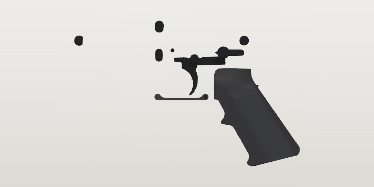
- Weight
- 7 oz ± 0.5 oz Conflictpublished: Primary Arms, a seller, read Oct 5, 2026Its sources span 6.5 oz to 10.4 oz.
- Lowest price
- $60.99 at Alexander's Store, read Nov 18, 2026
- Maker's number
- 55CA6C5
- Colour
- Black (placeholder)
- Drawn as
- modelled
- Maker's page
- cmmg.com
In “Budget 16 in carbine”, a build on the start page, as it is.
Its figures
Every figure the site draws and checks it by, with where it came from. Open one for each source's reading, and why one is used where they differ.
The takedown pin head's diameter0.375 in 9.5 mmConfirmedWorked out: {rise-lpk.takedown_pin_head_d}
Worked out 0.375 in used
{rise-lpk.takedown_pin_head_d}, from the site owner
The Army drawing's pin (8448584), read for the Rise kit. CMMG's kit is sold as mil-spec (Wing Tactical: 'All parts meet or exceed Mil-Spec'); CMMG's laid-out photo shows the two domed heads.
The takedown pin head's thickness0.09 in ± 0.005 in 2.3 mmConfirmedWorked out: {rise-lpk.takedown_pin_head_t}
Worked out 0.09 in ± 0.005 in used
{rise-lpk.takedown_pin_head_t}, from the site owner
Drawing 8448584, as the Rise kit's.
The pivot pin head's diameter0.4 in ± 0.005 in 10.2 mmConfirmedWorked out: {rise-lpk.pivot_pin_head_d}
Worked out 0.4 in ± 0.005 in used
{rise-lpk.pivot_pin_head_d}, from the site owner
Drawing 8448621, as the Rise kit's.
The pivot pin head's flat from the pin's axis0.136 in ± 0.0025 in 3.4 mmConfirmedWorked out: {rise-lpk.pivot_pin_head_flat}
Worked out 0.1355 in ± 0.0025 in used
{rise-lpk.pivot_pin_head_flat}, from the site owner
Drawing 8448621, as the Rise kit's.
The pivot pin head's thickness0.18 in ± 0.005 in 4.6 mmConfirmedWorked out: {rise-lpk.pivot_pin_head_t}
Worked out 0.18 in ± 0.005 in used
{rise-lpk.pivot_pin_head_t}, from the site owner
Drawing 8448621, as the Rise kit's.
Takedown and pivot pin heads, spherical radius of the domed face0.38 in ± 0.005 in 9.7 mmConfirmedWorked out: {rise-lpk.pin_head_dome_r}
Worked out 0.38 in ± 0.005 in used
{rise-lpk.pin_head_dome_r}, from the site owner
Drawings 8448584 and 8448621, as the Rise kit's.
The selector's hub diameter0.48 in ± 0.005 in 12.2 mmConfirmedWorked out: {rise-lpk.selector_hub_d}
Worked out 0.48 in ± 0.005 in used
{rise-lpk.selector_hub_d}, from the site owner
Drawing 9381367, as the Rise kit's. CMMG's photo shows a selector of this pattern (a hub, a pointer, a serrated paddle).
Selector pointer tip, from the selector's axis0.34 in ± 0.005 in 8.6 mmConfirmedWorked out: {rise-lpk.selector_pointer_reach}
Worked out 0.34 in ± 0.005 in used
{rise-lpk.selector_pointer_reach}, from the site owner
Drawing 9381367, as the Rise kit's.
Selector pointer included angle60° ± 2°ConfirmedWorked out: {rise-lpk.selector_pointer_angle}
Worked out 60 deg ± 2 deg used
{rise-lpk.selector_pointer_angle}, from the site owner
Drawing 9381367, as the Rise kit's.
Selector paddle width0.25 in ± 0.005 in 6.3 mmConfirmedWorked out: {rise-lpk.selector_paddle_width}
Worked out 0.25 in ± 0.005 in used
{rise-lpk.selector_paddle_width}, from the site owner
Drawing 9381367, as the Rise kit's.
Selector paddle end, from the selector's axis0.81 in ± 0.005 in 20.6 mmConfirmedWorked out: {rise-lpk.selector_paddle_reach}
Worked out 0.81 in ± 0.005 in used
{rise-lpk.selector_paddle_reach}, from the site owner
Drawing 9381367, as the Rise kit's.
Selector paddle's stepped serrations, top step to the outermost step0.11 in ± 0.005 in 2.8 mmConfirmedWorked out: {rise-lpk.selector_serration_height}
Worked out 0.11 in ± 0.005 in used
{rise-lpk.selector_serration_height}, from the site owner
Drawing 9381367 View H, as the Rise kit's.
The selector lever's thickness0.25 in ± 0.005 in 6.3 mmConfirmedWorked out: {rise-lpk.selector_lever_t}
Worked out 0.25 in ± 0.005 in used
{rise-lpk.selector_lever_t}, from the site owner
Drawing 9381367 View H, as the Rise kit's (missing in both until 2026-11-03).
The bolt catch paddle's rear edge ahead of the takedown pin3.11 in ± 0.015 in 79 mmProvisionalWorked out: {rise-lpk.bolt_catch_paddle_rear_x}
Worked out 3.11 in ± 0.015 in used
{rise-lpk.bolt_catch_paddle_rear_x}, from the site owner
A mil-spec bolt catch in its lower, measured in the pin frame of a complete lower's photo for the Rise kit; CMMG's own catch isn't measured.
Bolt catch paddle, front edge, X3.455 in ± 0.015 in 87.8 mmProvisionalWorked out: {rise-lpk.bolt_catch_paddle_front_x}
Worked out 3.455 in ± 0.015 in used
{rise-lpk.bolt_catch_paddle_front_x}, from the site owner
As bolt_catch_paddle_rear_x.
Bolt catch paddle, bottom of its serrated face, Y0.306 in ± 0.015 in 7.8 mmProvisionalWorked out: {rise-lpk.bolt_catch_paddle_bottom_y}
Worked out 0.306 in ± 0.015 in used
{rise-lpk.bolt_catch_paddle_bottom_y}, from the site owner
As bolt_catch_paddle_rear_x.
Bolt catch paddle, top, Y0.774 in ± 0.015 in 19.7 mmProvisionalWorked out: {rise-lpk.bolt_catch_paddle_top_y}
Worked out 0.774 in ± 0.015 in used
{rise-lpk.bolt_catch_paddle_top_y}, from the site owner
As bolt_catch_paddle_rear_x.
Bolt catch plate thickness0.151 in ± 0.003 in 3.8 mmConfirmedWorked out: {rise-lpk.bolt_catch_t}
Worked out 0.151 in ± 0.003 in used
{rise-lpk.bolt_catch_t}, from the site owner
Drawing 8448628, as the Rise kit's.
The magazine release button's width (fore and aft)0.3 in 7.6 mmConfirmedWorked out: {rise-lpk.magazine_release_w}
Worked out 0.3 in used
{rise-lpk.magazine_release_w}, from the site owner
Drawing 8448636, as the Rise kit's. CMMG's photo shows the oval, grooved button.
The magazine release button's height0.5 in 12.7 mmConfirmedWorked out: {rise-lpk.magazine_release_h}
Worked out 0.5 in used
{rise-lpk.magazine_release_h}, from the site owner
Drawing 8448636, as the Rise kit's.
How far the button stands out of the receiver's body0.109 in ± 0.0064 in 2.8 mmProvisionalWorked out: {rise-lpk.magazine_release_standoff}
Worked out 0.109 in used
{rise-lpk.magazine_release_standoff}, from the site owner
Flush with the fence, from the body's face, as the Rise kit's (its ledger has the sentence).
The A2 grip's top face in the rifle frame, Y (level: the receiver's underside either side of its lug)-1.069 in ± 0.011 in -27.2 mmConfirmedWorked out: {std.ar15.deck_y} - {std.ar15.grip_seat_below_deck}
Worked out -1.0695 in ± 0.0115 in used
{std.ar15.deck_y} - {std.ar15.grip_seat_below_deck}, from the site owner
The grip's top face (9349127's datum -E-) against the receiver's underside. Looked at on two pin-framed photos of rifles with A2 grips, this line drawn on each: the seam between receiver and grip lies along it within about 0.02. What a lower's grip_seat_y reads (the M4E1's -1.443, its silhouette's lowest at the pin) is the lug's sloped face (std.ar15.grip_lug_face_from_pin: -1.418 at the pin's X), which stands in the grip's slot, and not what the grip's top bears on (docs/STATUS.md, 'Noticed, not yet acted on'). Aero's complete lower has its own A2 grip's top registered at -1.221 (aero-m4e1-lower.grip_top_y, extrapolated from 0.3 in below where the receiver hides it); its silhouette's notch between receiver and grip is at -1.10.
The A2 grip's front face (above its step) in the rifle frame, X1.175 in ± 0.015 in 29.8 mmConfirmedWorked out: {std.ar15.receiver_rear_x} + {std.ar15.grip_lug_front_from_rear_face}
Worked out 1.175 in ± 0.015 in used
{std.ar15.receiver_rear_x} + {std.ar15.grip_lug_front_from_rear_face}, from the site owner
The grip's upright front face against the rear face of the trigger guard's ears, where the lug ends. The same two photos have the grip's front face on this line; Aero's M4E1 has its own face at 1.14 to 1.17.
The A2 grip's front face: its top face down to the step where the front strap begins1.275 in ± 0.005 in 32.4 mmConfirmedStandard: US Army TDP drawing 9349127 (Grip, Pistol), rev J, sheet 1, frame 1 of 2 (the M16 package's PDF page 33; a copy on file): the side view, right of the front face; user-supplied scan (Distribution Statement F, Colt proprietary notice)
Standard “1.275 ±.005” used
US Army TDP drawing 9349127 (Grip, Pistol), rev J, sheet 1, frame 1 of 2 (the M16 package's PDF page 33; a copy on file): the side view, right of the front face; user-supplied scan (Distribution Statement F, Colt proprietary notice), from the site owner
Between the top face's line and the step's (a .06 R corner at its foot): 328.7 px apart on the scan (stroke centres 2413.8 and 2742.5), 257.8 px/in. The front view's block, stated .885, is 233 px across (263 px/in), and aero-m4e1-lower's ledger reads the side view's 1.390 at 263. NOT what the side view is scaled by: scaled so, the outline is larger than the A2 grips in two pin-framed photos (a service M4A1's and a commercial lower's: grip_height's note), on both of which the step under the grip's front face is 1.21 to 1.23 below the seam, where the drawn distance falls at the size those grips are (1.22). Either the callout spans something other than what it was taken to, or grips as made are short of it; the model follows the photos, and this stays here as read.
The A2 grip's axis from the vertical with its top face level (its bottom further back)30° ± 1°ConfirmedStandard: US Army TDP drawing 9349127 (Grip, Pistol), rev J, sheet 1, frame 1 of 2 (PDF page 33): the side view, between the top face and the lines square to the grip's axis; user-supplied scan (Distribution Statement F, Colt proprietary notice)
Standard “30° ±1°” used
US Army TDP drawing 9349127 (Grip, Pistol), rev J, sheet 1, frame 1 of 2 (PDF page 33): the side view, between the top face and the lines square to the grip's axis; user-supplied scan (Distribution Statement F, Colt proprietary notice), from the site owner
The screw bore is at 60° (basic) to the top face (Section C-C); the bottom view looks along it. On a standard lower the top face is level, so the side outline turns by this to stand the axis up.
The A2 grip's width over its knurl (Z)1.27 in ± 0.02 in 32.3 mmConfirmedStandard: US Army TDP drawing 9349127 (Grip, Pistol), rev J, sheet 1, frame 1 of 2 (PDF page 33): the bottom view, along the grip's axis; user-supplied scan (Distribution Statement F, Colt proprietary notice)
Standard “1.270 APPROX OVER KNURL” used
US Army TDP drawing 9349127 (Grip, Pistol), rev J, sheet 1, frame 1 of 2 (PDF page 33): the bottom view, along the grip's axis; user-supplied scan (Distribution Statement F, Colt proprietary notice), from the site owner
The drawing's 'APPROX' taken as ± 0.02 (as aero-m4e1-lower.grip_width, the same callout). What the bottom view's trace is scaled by across.
The A2 grip's top block, across (Z): what bears on the receiver0.885 in ± 0.015 in 22.5 mmConfirmedStandard: US Army TDP drawing 9349127 (Grip, Pistol), rev J, sheet 1, frame 1 of 2 (PDF page 33): the top view; user-supplied scan (Distribution Statement F, Colt proprietary notice)
Standard “.885 ±.015” used
US Army TDP drawing 9349127 (Grip, Pistol), rev J, sheet 1, frame 1 of 2 (PDF page 33): the top view; user-supplied scan (Distribution Statement F, Colt proprietary notice), from the site owner
The slot along it, where the receiver's lug stands, is .380 +.005 (the same view). What the front view's trace is scaled by.
The A2 grip's slot along its top, where the receiver's lug stands, width0.383 in ± 0.0025 in 9.7 mmConfirmedStandard: US Army TDP drawing 9349127 (Grip, Pistol), rev J, sheet 1, frame 1 of 2 (PDF page 33): the top view (-B-, the slot between the block's two walls); user-supplied scan (Distribution Statement F, Colt proprietary notice)
Standard “.380 +.005” used
US Army TDP drawing 9349127 (Grip, Pistol), rev J, sheet 1, frame 1 of 2 (PDF page 33): the top view (-B-, the slot between the block's two walls); user-supplied scan (Distribution Statement F, Colt proprietary notice), from the site owner
.380 to .385: the middle. Over the receiver's .375 lug (std.ar15.grip_lug_width) that is 0.004 a side, the drawing's own fit. CMMG's article: 'You may notice the open area on the pistol grip appears to be a dovetail design. This is done intentionally for the sake of a tighter fit.' The slot's own floor and rear are in the drawing's Section C-C (frame 2), not read: the model's slot stands that 0.004 off the lug's faces all round.
The A2 grip's top block, its corners' radius0.06 in ± 0.01 in 1.5 mmConfirmedStandard: US Army TDP drawing 9349127 (Grip, Pistol), rev J, sheet 1, frame 1 of 2 (PDF page 33): the front view (the block's two upper corners; the top view and the step under the front face have the same .06 ±.01 R); user-supplied scan (Distribution Statement F, Colt proprietary notice)
Standard “.06 ±.01 R 2 PLACES” used
US Army TDP drawing 9349127 (Grip, Pistol), rev J, sheet 1, frame 1 of 2 (PDF page 33): the front view (the block's two upper corners; the top view and the step under the front face have the same .06 ±.01 R); user-supplied scan (Distribution Statement F, Colt proprietary notice), from the site owner
What the model's edges are rounded by, all over: the drawing's Section D-D leaves the exterior contour to 'sample furnished by the contractor'.
A mil-spec rifle's A2 grip, its lowest point below the pin line4.923 in ± 0.02 in 125 mmProvisionalPhoto: US Marine Corps: M4A1 SOPMOD Block II, straight right side, 7607 px (public domain): its A2 grip, below the receiver
Photo 4.923 in ± 0.02 in used
US Marine Corps: M4A1 SOPMOD Block II, straight right side, 7607 px (public domain): its A2 grip, below the receiver, harvested
Scale: frame from the reviewed holes takedown, pivot (184.3 px/in, rms 0.000 in over 2 points). Read by −y_min in x [-2.6, 0.4] of the traced outline (tools/trace.py)
The grip's lowest point (its front lower corner), black against the photo's light ground. ± is two pixels (0.011) and the frame's scale.
Filled by the trace's measure of the US Marine Corps' photo of an M4A1 (tools/trace.py).
A mil-spec rifle's A2 grip, its rearmost point (the heel) behind the takedown pin2.109 in ± 0.02 in 53.6 mmProvisionalPhoto: US Marine Corps: M4A1 SOPMOD Block II, straight right side, 7607 px (public domain): its A2 grip, below the receiver
Photo 2.109 in ± 0.02 in used
US Marine Corps: M4A1 SOPMOD Block II, straight right side, 7607 px (public domain): its A2 grip, below the receiver, harvested
Scale: frame from the reviewed holes takedown, pivot (184.3 px/in, rms 0.000 in over 2 points). Read by −x_min in y [-5.2, -3.6] of the traced outline (tools/trace.py)
The grip's heel, the rearmost point of its lower rear corner.
Filled by the trace's measure of the US Marine Corps' photo of an M4A1 (tools/trace.py).
The A2 grip's height: its top face to its lowest point3.853 in ± 0.032 in 97.9 mmConflictWorked out: {.grip_bottom_below_pin} + {.grip_top_y}
Worked out 3.8535 in ± 0.0315 in used
{.grip_bottom_below_pin} + {.grip_top_y}, harvested
A service M4A1's A2 grip in its pin frame (its lowest point, read on the US Marine Corps' photo) below the receiver's underside where the Army's drawing puts it (grip_top_y), on which that photo and a second (a copy on file) have the seam. Aero's photo of its own complete lower has its A2 grip's lowest point at 4.93 ± 0.031 (aero-m4e1-lower.grip_bottom_y) against this photo's 4.923: two rifles, two photos.
Photo 3.976 in ± 0.08 in
US Army TDP drawing 9349127 (Grip, Pistol) rev J, frame 1 of 2 (the user's M16 TDP scan, PDF page 33): the side view, from the site owner
Scale: frame from the reviewed holes top_front, step (257.8 px/in, rms 0.000 in over 2 points). Read by height of the traced outline (tools/trace.py)
The side view's top face to its lowest point, at the scale its stated 1.275 gives (257.8 px/in). The ± covers the spread of the drawing's stated sizes (258 to 263 px/in: 2%).
A real grip on a real rifle, in a pin frame, and a second rifle's photo agrees within 0.01. The drawing's side view scaled by its stated 1.275 stands 0.12 in taller than both and 0.2 in further back at the heel: laid on the two photos it is plainly too large, so the 1.275 is not the drawn distance at the size real grips are (see grip_front_face_h).
usmc and drawing differ by 0.123 in beyond what each states it is good to.
What the side view's trace is scaled by, with grip_depth. The drawing's own stated size across the view (the front face, 1.275) scales it 3% larger than a service rifle's grip is: kept, not adopted.
The A2 grip's side outline, fore and aft (its heel to its front face)3.284 in ± 0.03 in 83.4 mmConflictWorked out: {.grip_front_x} + {.grip_heel_behind_pin}
Worked out 3.284 in ± 0.03 in used
{.grip_front_x} + {.grip_heel_behind_pin}, harvested
A service M4A1's A2 grip in its pin frame (its heel, read on the US Marine Corps' photo) behind the receiver's face where the Army's drawing puts it (grip_front_x), on which both photos have the grip's front face.
Photo 3.491 in ± 0.07 in
US Army TDP drawing 9349127 (Grip, Pistol) rev J, frame 1 of 2 (the user's M16 TDP scan, PDF page 33): the side view, from the site owner
Scale: frame from the reviewed holes top_front, step (257.8 px/in, rms 0.000 in over 2 points). Read by width of the traced outline (tools/trace.py)
The side view's heel to its front face, at the same scale.
As grip_height. By this the drawing's side view is 273.7 px/in, by the height 266.0: 2.9% apart (the photo's grip leans about a degree nose-up of the drawing's, which shortens the one and lengthens the other); the trace takes their mean.
usmc and drawing differ by 0.207 in beyond what each states it is good to.
Trigger guard, overall length2.09 in ± 0.01 in 53.1 mmConfirmedStandard: US Army TDP drawing 8448588 (Guard, Trigger), rev E, sheet 1 of 1 (the M16 package's PDF page 60; a copy on file-8448588): the side view; user-supplied scan (Distribution Statement F, Colt proprietary notice)
Standard “2.09” used
US Army TDP drawing 8448588 (Guard, Trigger), rev E, sheet 1 of 1 (the M16 package's PDF page 60; a copy on file-8448588): the side view; user-supplied scan (Distribution Statement F, Colt proprietary notice), from the site owner
Trigger guard, its two cross holes, centre to centre1.844 in ± 0.002 in 46.8 mmConfirmedStandard: US Army TDP drawing 8448588 (Guard, Trigger), rev E, sheet 1 of 1 (PDF page 60): the side view; user-supplied scan (Distribution Statement F, Colt proprietary notice)
Standard “1.844 ±.002” used
US Army TDP drawing 8448588 (Guard, Trigger), rev E, sheet 1 of 1 (PDF page 60): the side view; user-supplied scan (Distribution Statement F, Colt proprietary notice), from the site owner
The receiver's drawing has the same 1.844 between its two guard holes, along the bore line (std.ar15.trigger_guard_hole_spacing): the guard lies level.
Trigger guard, the rear (roll pin) hole's centre from the rear end0.125 in ± 0.005 in 3.2 mmConfirmedStandard: US Army TDP drawing 8448588 (Guard, Trigger), rev E, sheet 1 of 1 (PDF page 60): the side view; user-supplied scan (Distribution Statement F, Colt proprietary notice)
Standard “.125” used
US Army TDP drawing 8448588 (Guard, Trigger), rev E, sheet 1 of 1 (PDF page 60): the side view; user-supplied scan (Distribution Statement F, Colt proprietary notice), from the site owner
The ends are full rounds about the holes (.125 R 2 PLACES): 2.09 = .125 + 1.844 + .125 within the drawing's rounding.
Trigger guard, the height of its two ends (the bosses the holes are in)0.25 in ± 0.01 in 6.3 mmConfirmedStandard: US Army TDP drawing 8448588 (Guard, Trigger), rev E, sheet 1 of 1 (PDF page 60): the side view; user-supplied scan (Distribution Statement F, Colt proprietary notice)
Standard “.25, 2 PLACES” used
US Army TDP drawing 8448588 (Guard, Trigger), rev E, sheet 1 of 1 (PDF page 60): the side view; user-supplied scan (Distribution Statement F, Colt proprietary notice), from the site owner
Trigger guard, the holes' centre line above its flat outer face0.125 in ± 0.005 in 3.2 mmConfirmedStandard: US Army TDP drawing 8448588 (Guard, Trigger), rev E, sheet 1 of 1 (PDF page 60): the side view, left; user-supplied scan (Distribution Statement F, Colt proprietary notice)
Standard “.125” used
US Army TDP drawing 8448588 (Guard, Trigger), rev E, sheet 1 of 1 (PDF page 60): the side view, left; user-supplied scan (Distribution Statement F, Colt proprietary notice), from the site owner
Trigger guard, the bar's thickness between its ends0.09 in ± 0.01 in 2.3 mmConfirmedStandard: US Army TDP drawing 8448588 (Guard, Trigger), rev E, sheet 1 of 1 (PDF page 60): the side view; user-supplied scan (Distribution Statement F, Colt proprietary notice)
Standard “.09” used
US Army TDP drawing 8448588 (Guard, Trigger), rev E, sheet 1 of 1 (PDF page 60): the side view; user-supplied scan (Distribution Statement F, Colt proprietary notice), from the site owner
Trigger guard, the radius of its ends, about the holes0.125 in ± 0.005 in 3.2 mmConfirmedStandard: US Army TDP drawing 8448588 (Guard, Trigger), rev E, sheet 1 of 1 (PDF page 60): the side view; user-supplied scan (Distribution Statement F, Colt proprietary notice)
Standard “.125 R 2 PLACES” used
US Army TDP drawing 8448588 (Guard, Trigger), rev E, sheet 1 of 1 (PDF page 60): the side view; user-supplied scan (Distribution Statement F, Colt proprietary notice), from the site owner
Trigger guard, the radius where each end runs down into the bar0.25 in ± 0.015 in 6.3 mmConfirmedStandard: US Army TDP drawing 8448588 (Guard, Trigger), rev E, sheet 1 of 1 (PDF page 60): the side view; user-supplied scan (Distribution Statement F, Colt proprietary notice)
Standard “.250 R ±.015” used
US Army TDP drawing 8448588 (Guard, Trigger), rev E, sheet 1 of 1 (PDF page 60): the side view; user-supplied scan (Distribution Statement F, Colt proprietary notice), from the site owner
Trigger guard, width (Z)0.43 in ± 0.003 in 10.9 mmConfirmedStandard: US Army TDP drawing 8448588 (Guard, Trigger), rev E, sheet 1 of 1 (PDF page 60): the plan view; user-supplied scan (Distribution Statement F, Colt proprietary notice)
Standard “.430 ±.003 (-B-)” used
US Army TDP drawing 8448588 (Guard, Trigger), rev E, sheet 1 of 1 (PDF page 60): the plan view; user-supplied scan (Distribution Statement F, Colt proprietary notice), from the site owner
Between the receiver's ears, 0.439 apart (std.ar15.trigger_guard_ear_gap).
Trigger guard, the rear (roll pin) hole's diameter0.129 in ± 0.001 in 3.3 mmConfirmedStandard: US Army TDP drawing 8448588 (Guard, Trigger), rev E, sheet 1 of 1 (PDF page 60): the side view; user-supplied scan (Distribution Statement F, Colt proprietary notice)
Standard “.1275 DIA +.0020, 90° ±4° C SINK BOTH SIDES TO .17 DIA” used
US Army TDP drawing 8448588 (Guard, Trigger), rev E, sheet 1 of 1 (PDF page 60): the side view; user-supplied scan (Distribution Statement F, Colt proprietary notice), from the site owner
The receiver's rear hole is the same .1275 +.0020 (std.ar15.trigger_guard_rear_hole_d).
Trigger guard, the plunger's bore across its front end, diameter0.128 in ± 0.0025 in 3.2 mmConfirmedStandard: US Army TDP drawing 8448588 (Guard, Trigger), rev E, sheet 1 of 1 (PDF page 60): the plan view; user-supplied scan (Distribution Statement F, Colt proprietary notice)
Standard “.125 DIA +.005 THRU, .166 DIA +.004 CBORE TO DEPTH SHOWN” used
US Army TDP drawing 8448588 (Guard, Trigger), rev E, sheet 1 of 1 (PDF page 60): the plan view; user-supplied scan (Distribution Statement F, Colt proprietary notice), from the site owner
The counterbore (.345 deep) opens on the side the plan view draws nearest the side view, and the assembly's drawing (8448587, PDF page 9) has the plunger's tip standing out of that side: the rifle's right, where the receiver's front hole is ('.125 DIA +.003 THRU THIS SIDE ONLY'). CMMG's article: 'the ball detent end on the trigger guard assembly will go on the end that is closet to the magazine well'.
Trigger guard, the spring pin's hole down through its front end, diameter0.064 in ± 0.0015 in 1.6 mmConfirmedStandard: US Army TDP drawing 8448588 (Guard, Trigger), rev E, sheet 1 of 1 (PDF page 60): the plan view; user-supplied scan (Distribution Statement F, Colt proprietary notice)
Standard “.062 DIA +.003 THRU BOTH SIDES” used
US Army TDP drawing 8448588 (Guard, Trigger), rev E, sheet 1 of 1 (PDF page 60): the plan view; user-supplied scan (Distribution Statement F, Colt proprietary notice), from the site owner
Trigger guard, the spring pin's hole from the side away from the plunger's tip (the left)0.06 in ± 0.003 in 1.5 mmConfirmedStandard: US Army TDP drawing 8448588 (Guard, Trigger), rev E, sheet 1 of 1 (PDF page 60): the plan view; user-supplied scan (Distribution Statement F, Colt proprietary notice)
Standard “.060 ±.003” used
US Army TDP drawing 8448588 (Guard, Trigger), rev E, sheet 1 of 1 (PDF page 60): the plan view; user-supplied scan (Distribution Statement F, Colt proprietary notice), from the site owner
Trigger guard, its edges' break0.01 in ± 0.005 in 0.3 mmConfirmedStandard: US Army TDP drawing 8448588 (Guard, Trigger), rev E, sheet 1 of 1 (PDF page 60): note 5; user-supplied scan (Distribution Statement F, Colt proprietary notice)
Standard “BREAK SHARP EDGES .005 +.010” used
US Army TDP drawing 8448588 (Guard, Trigger), rev E, sheet 1 of 1 (PDF page 60): note 5; user-supplied scan (Distribution Statement F, Colt proprietary notice), from the site owner
.005 to .015: the middle.
Where a standard lower holds the guard's front end: its front hole, Y-2.18 in ± 0.01 in -55.4 mmConfirmedWorked out: {std.ar15.trigger_guard_rear_y}
Worked out -2.18 in ± 0.01 in used
{std.ar15.trigger_guard_rear_y}, from the site owner
The receiver's drawing chains the 1.844 between its two guard holes along the bore line and gives one height (2.18) for the rear one; the guard's own holes are 1.844 apart, so both stand at one height. The reference CAD model has the front hole's spotface at Y -2.179 (std.ar15.trigger_guard_front_spotface_floor's reading). Drawn on the same two photos as the trigger (trigger_face_x), the guard's two holes land on the real guards' bosses within about 0.02 in, and its ends' rounds and the .250 R blends lie on theirs.
Mil-spec trigger, its fillet, edge and corner radii0.031 in ± 0.005 in 0.8 mmConfirmedStandard: US Army TDP drawing 8448592 (Trigger), rev L, sheet 1 of 1 (PDF page 43; a copy on file): note 3; user-supplied scan (Distribution Statement F, Colt proprietary notice)
Standard “FILLET, EDGE AND CORNER RADII .031, UNLESS OTHERWISE SPECIFIED” used
US Army TDP drawing 8448592 (Trigger), rev L, sheet 1 of 1 (PDF page 43; a copy on file): note 3; user-supplied scan (Distribution Statement F, Colt proprietary notice), from the site owner
An investment casting (note 1). Section A-A gives the blade's face its own radius across (.375 R ±.015), which isn't drawn.
The trigger at rest: how far it is turned about its pin from the Army drawing's side elevation (positive turns the blade forward)-1° ± 0.8°ProvisionalWorked out: {aero-m4e1-lower.trigger_rest_angle}
Worked out -1 deg ± 0.8 deg used
{aero-m4e1-lower.trigger_rest_angle}, from the site owner
Read on Aero's photo of its complete lower, a mil-spec trigger at rest in a lower with a mil-spec kit: the one reading on file. No photo of CMMG's trigger installed is on file.
The trigger's face ahead of the takedown pin (at rest in a standard lower)1.974 in ± 0.02 in 50.1 mmProvisionalWorked out: The traced side elevation (profiles.trigger, drawing 8448592) turned trigger_rest_angle about its pivot and stood on the standard's trigger pin hole (std.ar15.trigger_pin_x, std.ar15.trigger_pin_y): the deepest point of the blade's front edge, where a finger lies. Recomputed from the outline by app/tests/cmmg-lower-parts-kit.test.ts.
Worked out 1.9735 in ± 0.02 in used
The traced side elevation (profiles.trigger, drawing 8448592) turned trigger_rest_angle about its pivot and stood on the standard's trigger pin hole (std.ar15.trigger_pin_x, std.ar15.trigger_pin_y): the deepest point of the blade's front edge, where a finger lies. Recomputed from the outline by app/tests/cmmg-lower-parts-kit.test.ts., from the site owner
Aero's complete lower reads its own at 1.964 ± 0.015 on its photo (aero-m4e1-lower.trigger_face_x). The ± here is the rest angle's (0.8° at 0.95 in below the pin) and the outline's. Drawn on two pin-framed photos of rifles with mil-spec triggers, the blade's front edge lies on theirs within about 0.03 in.
What it goes with
By the way it mounts, and the figures each part on file states: a part whose figures say it doesn't fit is left out, and one whose fit can't be checked from what is published is marked. A check is against published figures, not a guarantee.
AR-15 lower parts kit
- Lower receivers
- Aero Precision M4E1 complete lower, A2 grip and M4 stock, Aero Precision M4E1 Stripped Lower Receiver, Battle Arms Development Workhorse stripped lower, BCM MK2 AR-15 Lower Receiver, Bear Creek Arsenal BC-15 Multi Caliber, Lower Receiver, Black Anodized, Geissele Automatics Super Duty AR-15 Lower Receiver - Stripped Lower, Palmetto State Armory AR-15 "Stealth" Stripped Lower Receiver
Prices on file
Each seller's latest reading of its own page: before tax and shipping, and not a quote. The pages are read again every night.
- Alexander's Store $60.99 Nov 18, 2026, in stock that day
- Impact Guns $61.99 Nov 21, 2026, in stock that day
- Wing Tactical $62.95 Nov 21, 2026, in stock that day
- CMMG $69.95 Nov 21, 2026, in stock that day
- Sportsman's Warehouse $69.99 Nov 21, 2026, in stock that day
- Scheels $69.99 Oct 5, 2026, in stock that day
- Rifle Supply $78.99 Nov 21, 2026, in stock that day
- Dirty Bird Industries $64.95 Nov 21, 2026, out of stock that day
- AR15Discounts $64.99 Nov 21, 2026, out of stock that day
- Right To Bear $67.95 Nov 21, 2026, out of stock that day