Lower receiver
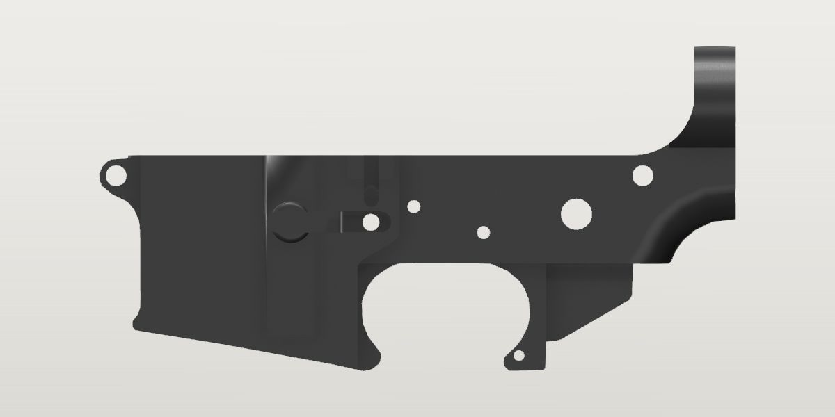
Battle Arms Development Workhorse stripped lower
Forged, TDP-compatible lower with a set-screw bolt catch pin, captured takedown detent and tension screw. Also made in ODG. Modelled from its traced side outline at the Army drawing's widths, with the inside a forged mil-spec lower shows: the fire-control pocket, the magazine well open through, the tower bored for the receiver extension and the pivot lug slotted for an upper's lug.
- Weight
- 8.22 oz Conflictpublished: Battle Arms Development, the maker, read Sep 30, 2026Its sources span 8.05 oz to 8.23 oz.
- Lowest price
- $125.00 at Redcon1 Tactical, read Nov 21, 2026
- Maker's number
- WH556-LR
- Colour
- Black (placeholder)
- Drawn as
- modelled
In “22RB .22 LR rifle”, a build on the start page, as it is.
Its figures
Every figure the site draws and checks it by, with where it came from. Open one for each source's reading, and why one is used where they differ.
Buffer tube (bore) axis above takedown pin center0.877 in ± 0.0015 in 22.3 mmConflictWorked out: {std.ar15.bore_axis_y}
Photo 0.849 in
not yet archived, from the project brief
Scale: not recorded in brief. Read by calibrated photo measurement; details not recorded in brief
The Workhorse photo agrees within 0.05 in (brief). The buffer tube is coaxial with the bore.
Worked out 0.8775 in ± 0.0015 in used
{std.ar15.bore_axis_y}, from the site owner
A forged mil-spec lower: the threaded hole's centre is the drawing's (.629 above the deck, the deck .250 above the pins).
The Army's drawings of the lower and of the upper give the same height (M6). M2's photo reads 0.03 low, and so do this lower's own photos (tower_top_above_pin): the mid-plane, scaled by the pins' near ends 0.44 in nearer the lens, reads about 2% short of what stands above the picture's centre.
magpul-photo and std differ by 0.028 in beyond what each states it is good to.
Magwell bottom opening center, X4.72 in 119.9 mmProvisionalPhoto: not recorded in brief
Photo “about (4.72, −2.07) in the rifle frame” used
not recorded in brief, from the project brief
Scale: not recorded in brief. Read by calibrated photo measurement
Magwell bottom opening center, Y-2.07 in -52.6 mmConflictPhoto: not recorded in brief
Photo “about (4.72, −2.07) in the rifle frame” used
not recorded in brief, from the project brief
Scale: not recorded in brief. Read by calibrated photo measurement
Photo -2.144 in ± 0.01 in
right side, Arsenal Engineering copy of the BAD photo, harvested
Scale: rifle frame from reviewed holes takedown (371.5,502.5) r=20px, pivot (1380.5,505.5) r=20px = takedown(0.0, 0.0), pivot(6.375, 0.0) (158.3 px/in). Read by silhouette y_min in x [4.7, 4.74] in frame coordinates; ± from hole-center and edge error
Outer silhouette of the magwell lip at the brief's x = 4.72.
Photo -2.16 in ± 0.01 in
left side, independent photo (Arsenal Engineering), harvested
Scale: rifle frame from reviewed holes takedown (1242.5,489.5) r=21px, pivot (223.5,488.5) r=22px = takedown(0.0, 0.0), pivot(6.375, 0.0) (159.8 px/in). Read by silhouette y_min in x [4.7, 4.74] in frame coordinates; ± from hole-center and edge error
Outer silhouette of the magwell lip at the brief's x = 4.72.
The brief's value pairs with its measured magazine hang (2.4 in below this edge). Both harvested photos read the outer lip lower and steeper, which may be a different reference line.
photo and right differ by 0.074 in beyond what each states it is good to.
photo and left differ by 0.09 in beyond what each states it is good to.
Magwell bottom edge rise toward the front5.5°ConflictPhoto: not recorded in brief
Photo “rises toward the front by about 5.5°” used
not recorded in brief, from the project brief
Scale: not recorded in brief. Read by calibrated photo measurement
Photo 9.85 deg ± 0.54 deg
right side, Arsenal Engineering copy of the BAD photo, harvested
Scale: rifle frame from reviewed holes takedown (371.5,502.5) r=20px, pivot (1380.5,505.5) r=20px = takedown(0.0, 0.0), pivot(6.375, 0.0) (158.3 px/in). Read by bottom-edge slope between x = 4.0 and 6.0 in (frame)
Outer silhouette of the magwell lip; the brief's 5.5° may be measured on the opening plane instead.
Photo 9.53 deg ± 0.54 deg
left side, independent photo (Arsenal Engineering), harvested
Scale: rifle frame from reviewed holes takedown (1242.5,489.5) r=21px, pivot (223.5,488.5) r=22px = takedown(0.0, 0.0), pivot(6.375, 0.0) (159.8 px/in). Read by bottom-edge slope between x = 4.0 and 6.0 in (frame)
Outer silhouette of the magwell lip; the brief's 5.5° may be measured on the opening plane instead.
The brief's value pairs with its measured magazine hang (2.4 in below this edge). Both harvested photos read the outer lip lower and steeper, which may be a different reference line.
photo and right differ by 4.3° beyond what each states it is good to.
photo and left differ by 4° beyond what each states it is good to.
Trigger guard front ear hole, X3.342 in ± 0.007 in 84.9 mmConflictWorked out: {std.ar15.trigger_guard_front_x}
Worked out 3.3425 in used
{std.ar15.trigger_guard_front_x}, from the site owner
The Workhorse is a TDP-compatible forging, so its hole is the standard's.
Photo 3.318 in ± 0.015 in
right side, Arsenal Engineering copy of the BAD photo, 1600px, harvested
Scale: takedown→pivot pin holes = 6.375 in (standard), 158.4 px/in. Read by Hough-circle hole centers; Umeyama similarity to the rifle frame (takedown at origin); ± is ~2 px
Photo 3.337 in ± 0.005 in
right side, Arsenal Engineering copy of the BAD photo, harvested
Scale: a pinhole camera fitted to the rims of 7 holes, 5 of them with the far rim seen through the near one (takedown, pivot, trigger, hammer at the ledger's places; selector (its y left to the fit), guard_rear (its x and y left to the fit), guard_front (tied to guard_rear)): lens 24.0 ± 0.8 in from the centre plane, standing over x 4.17, y -1.77, the side leaning 7.1 ± 1.2° to the sensor with its bottom nearer and 0.1° with the picture's right nearer; 158.8 px/in on the near face at the lens's foot; rims within 0.76 px rms. Read by x of the hole guard_front (guard_rear's, fitted with the camera, and the step to it: the rims' ± through the fit) of the traced outline (tools/trace.py)
The published standard (TDP 8448608). A camera fitted to the right photo (2026-10-05) with the guard's two holes left to the fit, this one 1.844 ahead of the rear as the drawing has them, reads it 3.337: 0.006 behind, inside both ±. The two-pin frame's 3.318 was 0.025 behind by the frame: see trigger_guard_rear_x.
tdp and right differ by 0.024 in beyond what each states it is good to.
External ear hole ahead of the trigger opening, on the right side: the left ear shows no hole (M1b's left reading, 3.325, was the ear face). Re-checked on a 3× crop in M3 (3.317).
Trigger guard front ear hole, Y-2.18 in ± 0.01 in -55.4 mmConflictWorked out: {std.ar15.trigger_guard_rear_y}
Photo -2.222 in ± 0.015 in
right side, Arsenal Engineering copy of the BAD photo, 1600px, harvested
Scale: takedown→pivot pin holes = 6.375 in (standard), 158.4 px/in. Read by Hough-circle hole centers; Umeyama similarity to the rifle frame (takedown at origin); ± is ~2 px
Worked out -2.18 in ± 0.01 in used
{std.ar15.trigger_guard_rear_y}, from the site owner
The drawing's side elevation has the guard's two holes on one centre line, 2.18 below the line through the pins; the reference CAD model has this one at Y -2.179.
The Army's drawing: on the rear hole's line. The right photo's -2.222 is the two-pin frame's, 0.04 low by the frame (see trigger_guard_rear_y); until 2026-10-05 it stood alone, and a trigger guard pinned into the two holes hung 1.3 degrees nose down.
right and tdp differ by 0.042 in beyond what each states it is good to.
Frame Y (up). Right side only (see trigger_guard_front_x).
Trigger guard rear ear hole, X1.498 in ± 0.01 in 38.1 mmConflictWorked out: {std.ar15.trigger_guard_rear_x}
Worked out 1.4985 in used
{std.ar15.trigger_guard_rear_x}, from the site owner
The Workhorse is a TDP-compatible forging, so its hole is the standard's.
Photo 1.469 in ± 0.015 in
right side, Arsenal Engineering copy of the BAD photo, 1600px, harvested
Scale: pin frame (takedown→pivot = 6.375 in, Hough-refined), 158.3 px/in. Read by centre of the hole's dark rim (603, 852) px, picked on a 3× gridded crop (Hough moves ±5 px across windows on a ~20 px hole)
Photo 1.459 in ± 0.015 in
left side, independent photo, 1600px, harvested
Scale: pin frame (takedown→pivot = 6.375 in, Hough-refined, mirrored), 159.8 px/in. Read by centre of the hole's dark rim (1009, 842) px, picked on a 3× gridded crop (Hough moves ±5 px across windows on a ~20 px hole)
Photo 1.493 in ± 0.005 in
right side, Arsenal Engineering copy of the BAD photo, harvested
Scale: a pinhole camera fitted to the rims of 7 holes, 5 of them with the far rim seen through the near one (takedown, pivot, trigger, hammer at the ledger's places; selector (its y left to the fit), guard_rear (its x and y left to the fit), guard_front (tied to guard_rear)): lens 24.0 ± 0.8 in from the centre plane, standing over x 4.17, y -1.77, the side leaning 7.1 ± 1.2° to the sensor with its bottom nearer and 0.1° with the picture's right nearer; 158.8 px/in on the near face at the lens's foot; rims within 0.76 px rms. Read by x of the hole guard_rear (fitted with the camera: the rims' ± through the fit) of the traced outline (tools/trace.py)
Photo 1.494 in ± 0.008 in
left side, independent photo (Arsenal Engineering), harvested
Scale: a pinhole camera fitted to the rims of 6 holes, 4 of them with the far rim seen through the near one (takedown, pivot, trigger, hammer at the ledger's places; selector (its y left to the fit), guard_rear (its x and y left to the fit)): lens 23.9 ± 0.8 in from the centre plane, standing over x 3.83, y -2.09, the side leaning 8.7 ± 2.3° to the sensor with its bottom nearer and 0.9° with the picture's left nearer; 160.1 px/in on the near face at the lens's foot; rims within 0.70 px rms. Read by x of the hole guard_rear (fitted with the camera: the rims' ± through the fit) of the traced outline (tools/trace.py)
The published standard (TDP 8448608). Through a camera fitted to each photo with this hole's place left to the fit (2026-10-05) it reads 1.493 and 1.494: 0.005 behind the drawing's, inside both ±. The two-pin frames' 1.469 and 1.459 were 0.03 to 0.04 behind, and that was the frame, not the part: two pins on one line fix one scale along it, and both photos were taken from 24 in with the receiver leaning 9 degrees to the sensor, its bottom nearer. The picture is 1.5% larger 2.2 in below the pins than on their line, about the point the lens stands over (4 in ahead of the takedown pin, level with the guard): this hole, 2.7 in behind that point, reads 0.04 further from it, less 0.01 for its rim being 0.11 in further from the lens than the pins' rims.
tdp and right differ by 0.029 in beyond what each states it is good to.
tdp and left differ by 0.039 in beyond what each states it is good to.
right and trace-right-holes differ by 0.024 in beyond what each states it is good to.
right and trace-left-holes differ by 0.025 in beyond what each states it is good to.
left and trace-right-holes differ by 0.034 in beyond what each states it is good to.
left and trace-left-holes differ by 0.035 in beyond what each states it is good to.
M1b's Hough fit (1.589 / 1.572) had locked onto the ear's face ~0.12 in ahead of the hole in both photos; found in M3 when the MOE guard didn't match the user's installed photos. The real rear hole is the ~0.13 in roll-pin hole (a published 0.1275 in).
Trigger guard rear ear hole, Y-2.18 in ± 0.01 in -55.4 mmConflictWorked out: {std.ar15.trigger_guard_rear_y}
Worked out -2.18 in used
{std.ar15.trigger_guard_rear_y}, from the site owner
The Workhorse is a TDP-compatible forging, so its hole is the standard's.
Photo -2.204 in ± 0.015 in
right side, Arsenal Engineering copy of the BAD photo, 1600px, harvested
Scale: pin frame (takedown→pivot = 6.375 in, Hough-refined), 158.3 px/in. Read by centre of the hole's dark rim (603, 852) px, picked on a 3× gridded crop (Hough moves ±5 px across windows on a ~20 px hole)
Photo -2.207 in ± 0.015 in
left side, independent photo, 1600px, harvested
Scale: pin frame (takedown→pivot = 6.375 in, Hough-refined, mirrored), 159.8 px/in. Read by centre of the hole's dark rim (1009, 842) px, picked on a 3× gridded crop (Hough moves ±5 px across windows on a ~20 px hole)
Photo -2.194 in ± 0.007 in
right side, Arsenal Engineering copy of the BAD photo, harvested
Scale: a pinhole camera fitted to the rims of 7 holes, 5 of them with the far rim seen through the near one (takedown, pivot, trigger, hammer at the ledger's places; selector (its y left to the fit), guard_rear (its x and y left to the fit), guard_front (tied to guard_rear)): lens 24.0 ± 0.8 in from the centre plane, standing over x 4.17, y -1.77, the side leaning 7.1 ± 1.2° to the sensor with its bottom nearer and 0.1° with the picture's right nearer; 158.8 px/in on the near face at the lens's foot; rims within 0.76 px rms. Read by y of the hole guard_rear (fitted with the camera: the rims' ± through the fit) of the traced outline (tools/trace.py)
Photo -2.192 in ± 0.013 in
left side, independent photo (Arsenal Engineering), harvested
Scale: a pinhole camera fitted to the rims of 6 holes, 4 of them with the far rim seen through the near one (takedown, pivot, trigger, hammer at the ledger's places; selector (its y left to the fit), guard_rear (its x and y left to the fit)): lens 23.9 ± 0.8 in from the centre plane, standing over x 3.83, y -2.09, the side leaning 8.7 ± 2.3° to the sensor with its bottom nearer and 0.9° with the picture's left nearer; 160.1 px/in on the near face at the lens's foot; rims within 0.70 px rms. Read by y of the hole guard_rear (fitted with the camera: the rims' ± through the fit) of the traced outline (tools/trace.py)
The published standard (TDP 8448608: 2.18, two places). Through the cameras, with its place left to the fit, the two photos read it -2.194 ± 0.007 and -2.192 ± 0.013: 0.013 below the drawing's, at the edge of its ± and inside theirs. Those fits lean 7.1 ± 1.2 and 8.7 ± 2.3 degrees; with every hole at the drawing's place the fits lean 9.3 and 10.6, as well within the rims' ±: whether that last hundredth is the part's or the lean's the photos can't say. The two-pin frames' -2.204 and -2.207 were low by the frame: 1.5% of 2.18 in is 0.03.
tdp and left differ by 0.027 in beyond what each states it is good to.
Frame Y (up). See trigger_guard_rear_x.
Trigger pin hole center (external), X1.928 in ± 0.004 in 49 mmConfirmedWorked out: {std.ar15.trigger_pin_x}
Worked out 1.928 in used
{std.ar15.trigger_pin_x}, from the site owner
The Workhorse is a TDP-compatible forging, so its hole is the standard's.
Photo 1.914 in ± 0.015 in
right side, Arsenal Engineering copy of the BAD photo, 1600px, harvested
Scale: takedown→pivot pin holes = 6.375 in (standard), 158.4 px/in. Read by Hough-circle hole centers; Umeyama similarity to the rifle frame (takedown at origin); ± is ~2 px
Photo 1.916 in ± 0.015 in
left side, independent photo, 1600px, harvested
Scale: takedown→pivot pin holes = 6.375 in (standard), 159.7 px/in. Read by Hough-circle hole centers, mirrored view; Umeyama similarity to the rifle frame; ± is ~2 px
The published standard (TDP 8448608), and since 2026-10-05 one of the holes each photo's camera is fitted to: its rim lies within a pixel of where the camera puts the drawing's. The two-pin frames' 1.914 and 1.916 were 0.013 behind by the frame (see trigger_guard_rear_x; on the right its origin also stood on the takedown hole's rim, the floor of a spotface 0.04 in below the face, which reads 0.007 toward the lens).
The lower, rearward of the two fire-control pin holes (the trigger tail sits against the selector). External hole position only.
Trigger pin hole center (external), Y-0.689 in ± 0.0035 in -17.5 mmConfirmedWorked out: {std.ar15.trigger_pin_y}
Photo -0.678 in ± 0.015 in
right side, Arsenal Engineering copy of the BAD photo, 1600px, harvested
Scale: takedown→pivot pin holes = 6.375 in (standard), 158.4 px/in. Read by Hough-circle hole centers; Umeyama similarity to the rifle frame (takedown at origin); ± is ~2 px
Photo -0.689 in ± 0.015 in
left side, independent photo, 1600px, harvested
Scale: takedown→pivot pin holes = 6.375 in (standard), 159.7 px/in. Read by Hough-circle hole centers, mirrored view; Umeyama similarity to the rifle frame; ± is ~2 px
Worked out -0.689 in used
{std.ar15.trigger_pin_y}, from the site owner
The Workhorse is a TDP-compatible forging, so its hole is the standard's.
The drawing dimensions it (2026-10-03: .375 and .3140 below the pin line); the left photo reads the same, the right 0.011 high. Until then the right photo's, for its cleaner hole edges.
Frame Y (up).
Hammer pin hole center (external), X2.771 in ± 0.004 in 70.4 mmConfirmedWorked out: {std.ar15.hammer_pin_x}
Worked out 2.771 in used
{std.ar15.hammer_pin_x}, from the site owner
The Workhorse is a TDP-compatible forging, so its hole is the standard's.
Photo 2.753 in ± 0.015 in
right side, Arsenal Engineering copy of the BAD photo, 1600px, harvested
Scale: takedown→pivot pin holes = 6.375 in (standard), 158.4 px/in. Read by Hough-circle hole centers; Umeyama similarity to the rifle frame (takedown at origin); ± is ~2 px
Photo 2.768 in ± 0.015 in
left side, independent photo, 1600px, harvested
Scale: takedown→pivot pin holes = 6.375 in (standard), 159.7 px/in. Read by Hough-circle hole centers, mirrored view; Umeyama similarity to the rifle frame; ± is ~2 px
The published standard (TDP 8448608), and since 2026-10-05 one of the holes each photo's camera is fitted to: its rim lies within a pixel of where the camera puts the drawing's. The two-pin frames read 2.753 and 2.768: by the frame (see trigger_pin_x).
The upper, forward fire-control pin hole. External hole position only.
Hammer pin hole center (external), Y-0.375 in ± 0.002 in -9.5 mmConfirmedWorked out: {std.ar15.hammer_pin_y}
Photo -0.361 in ± 0.015 in
right side, Arsenal Engineering copy of the BAD photo, 1600px, harvested
Scale: takedown→pivot pin holes = 6.375 in (standard), 158.4 px/in. Read by Hough-circle hole centers; Umeyama similarity to the rifle frame (takedown at origin); ± is ~2 px
Photo -0.376 in ± 0.015 in
left side, independent photo, 1600px, harvested
Scale: takedown→pivot pin holes = 6.375 in (standard), 159.7 px/in. Read by Hough-circle hole centers, mirrored view; Umeyama similarity to the rifle frame; ± is ~2 px
Worked out -0.375 in used
{std.ar15.hammer_pin_y}, from the site owner
The Workhorse is a TDP-compatible forging, so its hole is the standard's.
The drawing dimensions it (2026-10-03: .375 below the pin line); the left photo reads the same, the right 0.014 high. Until then the right photo's, for its cleaner hole edges.
Frame Y (up).
Safety selector hole center, X0.803 in ± 0.004 in 20.4 mmConfirmedWorked out: {std.ar15.selector_x}
Worked out 0.803 in used
{std.ar15.selector_x}, from the site owner
The Workhorse is a TDP-compatible forging, so its hole is the standard's.
Photo 0.79 in ± 0.015 in
right side, Arsenal Engineering copy of the BAD photo, 1600px, harvested
Scale: takedown→pivot pin holes = 6.375 in (standard), 158.4 px/in. Read by Hough-circle hole centers; Umeyama similarity to the rifle frame (takedown at origin); ± is ~2 px
Photo 0.789 in ± 0.015 in
left side, independent photo, 1600px, harvested
Scale: takedown→pivot pin holes = 6.375 in (standard), 159.7 px/in. Read by Hough-circle hole centers, mirrored view; Umeyama similarity to the rifle frame; ± is ~2 px
The published standard (TDP 8448608), and since 2026-10-05 one of the holes each photo's camera is fitted to: its rim lies within a pixel of where the camera puts the drawing's. The two-pin frames' 0.790 and 0.789 were 0.013 behind by the frame (see trigger_pin_x).
Places the LPK selector.
Safety selector hole center, Y-0.466 in ± 0.004 in -11.8 mmCorroboratedPhoto: right side, Arsenal Engineering copy of the BAD photo
Photo -0.466 in ± 0.015 in
right side, Arsenal Engineering copy of the BAD photo, 1600px, harvested
Scale: takedown→pivot pin holes = 6.375 in (standard), 158.4 px/in. Read by Hough-circle hole centers; Umeyama similarity to the rifle frame (takedown at origin); ± is ~2 px
Photo -0.457 in ± 0.015 in
left side, independent photo, 1600px, harvested
Scale: takedown→pivot pin holes = 6.375 in (standard), 159.7 px/in. Read by Hough-circle hole centers, mirrored view; Umeyama similarity to the rifle frame; ± is ~2 px
Photo -0.466 in ± 0.004 in used
right side, Arsenal Engineering copy of the BAD photo, harvested
Scale: a pinhole camera fitted to the rims of 7 holes, 5 of them with the far rim seen through the near one (takedown, pivot, trigger, hammer at the ledger's places; selector (its y left to the fit), guard_rear (its x and y left to the fit), guard_front (tied to guard_rear)): lens 24.0 ± 0.8 in from the centre plane, standing over x 4.17, y -1.77, the side leaning 7.1 ± 1.2° to the sensor with its bottom nearer and 0.1° with the picture's right nearer; 158.8 px/in on the near face at the lens's foot; rims within 0.76 px rms. Read by y of the hole selector (fitted with the camera: the rims' ± through the fit) of the traced outline (tools/trace.py)
Photo -0.464 in ± 0.004 in
left side, independent photo (Arsenal Engineering), harvested
Scale: a pinhole camera fitted to the rims of 6 holes, 4 of them with the far rim seen through the near one (takedown, pivot, trigger, hammer at the ledger's places; selector (its y left to the fit), guard_rear (its x and y left to the fit)): lens 23.9 ± 0.8 in from the centre plane, standing over x 3.83, y -2.09, the side leaning 8.7 ± 2.3° to the sensor with its bottom nearer and 0.9° with the picture's left nearer; 160.1 px/in on the near face at the lens's foot; rims within 0.70 px rms. Read by y of the hole selector (fitted with the camera: the rims' ± through the fit) of the traced outline (tools/trace.py)
Read through the camera fitted to each photo (2026-10-05), its height the one coordinate of the fire-control holes left to the fit: -0.466 and -0.464. The two-pin frames read -0.466 and -0.457.
Frame Y (up).
Rear of the buffer-tower ring behind the takedown pin1.125 in ± 0.005 in 28.6 mmConflictWorked out: -{std.ar15.receiver_rear_x}
Photo 1.162 in ± 0.01 in
right side, Arsenal Engineering copy of the BAD photo, harvested
Scale: rifle frame from reviewed holes takedown (371.5,502.5) r=20px, pivot (1380.5,505.5) r=20px = takedown(0.0, 0.0), pivot(6.375, 0.0) (158.3 px/in). Read by silhouette x_min in frame coordinates (negated); ± from hole-center and edge error
Rearmost point: the buffer-tower ring.
Photo 1.147 in ± 0.01 in
left side, independent photo (Arsenal Engineering), harvested
Scale: rifle frame from reviewed holes takedown (1242.5,489.5) r=21px, pivot (223.5,488.5) r=22px = takedown(0.0, 0.0), pivot(6.375, 0.0) (159.8 px/in). Read by silhouette x_min in frame coordinates (negated); ± from hole-center and edge error
Rearmost point: the buffer-tower ring.
Worked out 1.125 in ± 0.005 in used
-{std.ar15.receiver_rear_x}, from the site owner
The ring's rear is the receiver's rear face, one plane where the end plate bears (rear_face_x reads it 1.134 and 1.136 below the ring).
The Army's drawing (7.503 −.006 from the pivot pin). The two photos read the ring's rim, which stands 0.25 in nearer the lens than the pins they are scaled by, so 0.02 to 0.04 far; the face below the ring, level with the pins, reads within 0.01 of the drawing.
right and std differ by 0.037 in beyond what each states it is good to.
left and std differ by 0.022 in beyond what each states it is good to.
Front of the pivot-pin lug ahead of the takedown pin6.58 in ± 0.01 in 167.1 mmCorroboratedPhoto: right side, Arsenal Engineering copy of the BAD photo
Photo 6.574 in ± 0.017 in
right side, Arsenal Engineering copy of the BAD photo, harvested
Scale: rifle frame from reviewed holes takedown (371.5,502.5) r=20px, pivot (1380.5,505.5) r=20px = takedown(0.0, 0.0), pivot(6.375, 0.0) (158.3 px/in). Read by silhouette x_max in frame coordinates; ± from hole-center and edge error
Front of the pivot-pin lug.
Photo 6.56 in ± 0.017 in
left side, independent photo (Arsenal Engineering), harvested
Scale: rifle frame from reviewed holes takedown (1242.5,489.5) r=21px, pivot (223.5,488.5) r=22px = takedown(0.0, 0.0), pivot(6.375, 0.0) (159.8 px/in). Read by silhouette x_max in frame coordinates; ± from hole-center and edge error
Front of the pivot-pin lug.
Photo 6.58 in ± 0.01 in used
right side, Arsenal Engineering copy of the BAD photo, harvested
Scale: a pinhole camera fitted to the rims of 7 holes, 5 of them with the far rim seen through the near one (takedown, pivot, trigger, hammer, guard_rear, guard_front at the ledger's places; selector (its y left to the fit)): lens 24.1 ± 0.9 in from the centre plane, standing over x 4.18, y -1.77, the side leaning 9.3 ± 0.4° to the sensor with its bottom nearer and 0.1° with the picture's right nearer; 158.3 px/in on the near face at the lens's foot; rims within 0.86 px rms. Read by x_max of the traced outline (tools/trace.py)
Front of the pivot-pin lug.
Photo 6.576 in ± 0.01 in
left side, independent photo (Arsenal Engineering), harvested
Scale: a pinhole camera fitted to the rims of 6 holes, 4 of them with the far rim seen through the near one (takedown, pivot, trigger, hammer, guard_rear at the ledger's places; selector (its y left to the fit)): lens 23.9 ± 0.8 in from the centre plane, standing over x 3.82, y -2.09, the side leaning 10.6 ± 0.4° to the sensor with its bottom nearer and 0.8° with the picture's left nearer; 159.7 px/in on the near face at the lens's foot; rims within 0.72 px rms. Read by x_max of the traced outline (tools/trace.py)
Front of the pivot-pin lug.
Through the camera fitted to each photo (2026-10-05): 6.580 and 6.576. The two-pin frames read 6.574 and 6.560: level with the pins, where that frame is good.
Top of the buffer-tower ring above the pin line1.573 in ± 0.0065 in 40 mmConflictWorked out: {std.ar15.buffer_tower_top_y}
Photo 1.543 in ± 0.01 in
right side, Arsenal Engineering copy of the BAD photo, harvested
Scale: rifle frame from reviewed holes takedown (371.5,502.5) r=20px, pivot (1380.5,505.5) r=20px = takedown(0.0, 0.0), pivot(6.375, 0.0) (158.3 px/in). Read by silhouette y_max in frame coordinates; ± from hole-center and edge error
Top of the buffer-tower ring.
Photo 1.537 in ± 0.01 in
left side, independent photo (Arsenal Engineering), harvested
Scale: rifle frame from reviewed holes takedown (1242.5,489.5) r=21px, pivot (223.5,488.5) r=22px = takedown(0.0, 0.0), pivot(6.375, 0.0) (159.8 px/in). Read by silhouette y_max in frame coordinates; ± from hole-center and edge error
Top of the buffer-tower ring.
Worked out 1.5735 in ± 0.0065 in used
{std.ar15.buffer_tower_top_y}, from the site owner
The Army's drawing (1.325 above the deck). The two photos read the ring's top on the mid-plane, 0.44 in further from the lens than the pins they are scaled by, so 0.03 short; with the ring's radius they gave M2's low axis.
right and std differ by 0.03 in beyond what each states it is good to.
left and std differ by 0.036 in beyond what each states it is good to.
Receiver top deck above the pin line0.248 in ± 0.0015 in 6.3 mmConfirmedWorked out: {std.ar15.deck_y}
Photo 0.254 in ± 0.009 in
right side, Arsenal Engineering copy of the BAD photo, harvested
Scale: rifle frame from reviewed holes takedown (371.5,502.5) r=20px, pivot (1380.5,505.5) r=20px = takedown(0.0, 0.0), pivot(6.375, 0.0) (158.3 px/in). Read by silhouette y_max in x [0.6, 5.8] in frame coordinates; ± from hole-center and edge error
Receiver top edge between the tower and the pivot lug (where the upper sits).
Photo 0.247 in ± 0.009 in
left side, independent photo (Arsenal Engineering), harvested
Scale: rifle frame from reviewed holes takedown (1242.5,489.5) r=21px, pivot (223.5,488.5) r=22px = takedown(0.0, 0.0), pivot(6.375, 0.0) (159.8 px/in). Read by silhouette y_max in x [0.6, 5.8] in frame coordinates; ± from hole-center and edge error
Receiver top edge between the tower and the pivot lug (where the upper sits).
Worked out 0.2485 in ± 0.0015 in used
{std.ar15.deck_y}, from the site owner
The Army's drawing: .250 −.003 above the line through the pins.
Photo 0.244 in ± 0.01 in
right side, Arsenal Engineering copy of the BAD photo, harvested
Scale: a pinhole camera fitted to the rims of 7 holes, 5 of them with the far rim seen through the near one (takedown, pivot, trigger, hammer, guard_rear, guard_front at the ledger's places; selector (its y left to the fit)): lens 24.1 ± 0.9 in from the centre plane, standing over x 4.18, y -1.77, the side leaning 9.3 ± 0.4° to the sensor with its bottom nearer and 0.1° with the picture's right nearer; 158.3 px/in on the near face at the lens's foot; rims within 0.86 px rms. Read by y_max in x [0.6, 2.8] of the traced outline (tools/trace.py)
The receiver's top edge behind the magazine well (clear of the roll along the well's top, which stands nearer the lens).
Photo 0.246 in ± 0.009 in
left side, independent photo (Arsenal Engineering), harvested
Scale: a pinhole camera fitted to the rims of 6 holes, 4 of them with the far rim seen through the near one (takedown, pivot, trigger, hammer, guard_rear at the ledger's places; selector (its y left to the fit)): lens 23.9 ± 0.8 in from the centre plane, standing over x 3.82, y -2.09, the side leaning 10.6 ± 0.4° to the sensor with its bottom nearer and 0.8° with the picture's left nearer; 159.7 px/in on the near face at the lens's foot; rims within 0.72 px rms. Read by y_max in x [0.6, 2.8] of the traced outline (tools/trace.py)
The receiver's top edge behind the magazine well (clear of the roll along the well's top, which stands nearer the lens).
The Army's drawing, since 2026-10-12: the deck is the seat every upper sits on, and the model's is drawn on the drawing's plane (pipeline/blender/lib.py deck_outline). The right photo's 0.254, adopted until then, is the top of the roll along the well's right wall, which stands 0.11 in nearer the lens than the body; behind the well the two photos' cameras read the deck 0.244 and 0.246, either side of the drawing within their ±. The 22RB's receiver had been cut to the 0.254 and is on the drawing's plane too.
Lowest point below the pin line (trigger-guard ears)2.368 in ± 0.01 in 60.1 mmConflictPhoto: right side, Arsenal Engineering copy of the BAD photo
Photo 2.4 in ± 0.011 in
right side, Arsenal Engineering copy of the BAD photo, harvested
Scale: rifle frame from reviewed holes takedown (371.5,502.5) r=20px, pivot (1380.5,505.5) r=20px = takedown(0.0, 0.0), pivot(6.375, 0.0) (158.3 px/in). Read by silhouette y_min in frame coordinates (negated); ± from hole-center and edge error
Lowest point (trigger-guard ears / magwell front).
Photo 2.409 in ± 0.011 in
left side, independent photo (Arsenal Engineering), harvested
Scale: rifle frame from reviewed holes takedown (1242.5,489.5) r=21px, pivot (223.5,488.5) r=22px = takedown(0.0, 0.0), pivot(6.375, 0.0) (159.8 px/in). Read by silhouette y_min in frame coordinates (negated); ± from hole-center and edge error
Lowest point (trigger-guard ears / magwell front).
Photo 2.368 in ± 0.01 in used
right side, Arsenal Engineering copy of the BAD photo, harvested
Scale: a pinhole camera fitted to the rims of 7 holes, 5 of them with the far rim seen through the near one (takedown, pivot, trigger, hammer, guard_rear, guard_front at the ledger's places; selector (its y left to the fit)): lens 24.1 ± 0.9 in from the centre plane, standing over x 4.18, y -1.77, the side leaning 9.3 ± 0.4° to the sensor with its bottom nearer and 0.1° with the picture's right nearer; 158.3 px/in on the near face at the lens's foot; rims within 0.86 px rms. Read by −y_min of the traced outline (tools/trace.py)
Lowest point: the trigger guard's ears and the well's rear lip.
Photo 2.375 in ± 0.01 in
left side, independent photo (Arsenal Engineering), harvested
Scale: a pinhole camera fitted to the rims of 6 holes, 4 of them with the far rim seen through the near one (takedown, pivot, trigger, hammer, guard_rear at the ledger's places; selector (its y left to the fit)): lens 23.9 ± 0.8 in from the centre plane, standing over x 3.82, y -2.09, the side leaning 10.6 ± 0.4° to the sensor with its bottom nearer and 0.8° with the picture's left nearer; 159.7 px/in on the near face at the lens's foot; rims within 0.72 px rms. Read by −y_min of the traced outline (tools/trace.py)
Lowest point: the trigger guard's ears and the well's rear lip.
Through the camera fitted to each photo (2026-10-05): 2.368 and 2.375. The two-pin frames' 2.400 and 2.409 were 0.03 long by the frame: the picture is 1.6% larger 2.4 in below the pins than on their line.
right and trace-right differ by 0.032 in beyond what each states it is good to.
right and trace-left differ by 0.025 in beyond what each states it is good to.
left and trace-right differ by 0.041 in beyond what each states it is good to.
left and trace-left differ by 0.034 in beyond what each states it is good to.
Grip shelf, upper-rear end, Y-1.55 in ± 0.01 in -39.4 mmConflictPhoto: right side, Arsenal Engineering copy of the BAD photo
Photo -1.563 in ± 0.01 in
right side, Arsenal Engineering copy of the BAD photo, harvested
Scale: rifle frame from reviewed holes takedown (371.5,502.5) r=20px, pivot (1380.5,505.5) r=20px = takedown(0.0, 0.0), pivot(6.375, 0.0) (158.3 px/in). Read by silhouette y_min in x [0.18, 0.24] in frame coordinates; ± from hole-center and edge error
Upper-rear end of the sloped grip-contact shelf (just ahead of the step at x ≈ 0.15).
Photo -1.567 in ± 0.01 in
left side, independent photo (Arsenal Engineering), harvested
Scale: rifle frame from reviewed holes takedown (1242.5,489.5) r=21px, pivot (223.5,488.5) r=22px = takedown(0.0, 0.0), pivot(6.375, 0.0) (159.8 px/in). Read by silhouette y_min in x [0.18, 0.24] in frame coordinates; ± from hole-center and edge error
Upper-rear end of the sloped grip-contact shelf (just ahead of the step at x ≈ 0.15).
Photo -1.55 in ± 0.01 in used
right side, Arsenal Engineering copy of the BAD photo, harvested
Scale: a pinhole camera fitted to the rims of 7 holes, 5 of them with the far rim seen through the near one (takedown, pivot, trigger, hammer, guard_rear, guard_front at the ledger's places; selector (its y left to the fit)): lens 24.1 ± 0.9 in from the centre plane, standing over x 4.18, y -1.77, the side leaning 9.3 ± 0.4° to the sensor with its bottom nearer and 0.1° with the picture's right nearer; 158.3 px/in on the near face at the lens's foot; rims within 0.86 px rms. Read by y_min in x [0.18, 0.24] of the traced outline (tools/trace.py)
Upper-rear end of the lug's sloped face (just ahead of its rear face).
Photo -1.545 in ± 0.01 in
left side, independent photo (Arsenal Engineering), harvested
Scale: a pinhole camera fitted to the rims of 6 holes, 4 of them with the far rim seen through the near one (takedown, pivot, trigger, hammer, guard_rear at the ledger's places; selector (its y left to the fit)): lens 23.9 ± 0.8 in from the centre plane, standing over x 3.82, y -2.09, the side leaning 10.6 ± 0.4° to the sensor with its bottom nearer and 0.8° with the picture's left nearer; 159.7 px/in on the near face at the lens's foot; rims within 0.72 px rms. Read by y_min in x [0.18, 0.24] of the traced outline (tools/trace.py)
Upper-rear end of the lug's sloped face (just ahead of its rear face).
Through the camera fitted to each photo (2026-10-05), on the lug's near side: -1.550 and -1.545; the two-pin frames read -1.563 and -1.567.
left and trace-left differ by 0.022 in beyond what each states it is good to.
The bottom of the step behind the tang, where the sloped web starts. Not where the grip seats (see grip_seat_y): the web covers the grip's top from the side.
Receiver underside behind the step (where a grip's flat top bears), Y-1.072 in ± 0.01 in -27.2 mmConflictPhoto: right side, Arsenal Engineering copy of the BAD photo
Photo -1.096 in ± 0.01 in
right side, Arsenal Engineering copy of the BAD photo, harvested
Scale: rifle frame from reviewed holes takedown (371.5,502.5) r=20px, pivot (1380.5,505.5) r=20px = takedown(0.0, 0.0), pivot(6.375, 0.0) (158.3 px/in). Read by silhouette y_min in x [-0.2, 0.08] in frame coordinates; ± from hole-center and edge error
The receiver's underside just behind the step (the tang), where a grip's flat top bears.
Photo -1.092 in ± 0.01 in
left side, independent photo (Arsenal Engineering), harvested
Scale: rifle frame from reviewed holes takedown (1242.5,489.5) r=21px, pivot (223.5,488.5) r=22px = takedown(0.0, 0.0), pivot(6.375, 0.0) (159.8 px/in). Read by silhouette y_min in x [-0.2, 0.08] in frame coordinates; ± from hole-center and edge error
The receiver's underside just behind the step (the tang), where a grip's flat top bears.
Photo -1.072 in ± 0.01 in used
right side, Arsenal Engineering copy of the BAD photo, harvested
Scale: a pinhole camera fitted to the rims of 7 holes, 5 of them with the far rim seen through the near one (takedown, pivot, trigger, hammer, guard_rear, guard_front at the ledger's places; selector (its y left to the fit)): lens 24.1 ± 0.9 in from the centre plane, standing over x 4.18, y -1.77, the side leaning 9.3 ± 0.4° to the sensor with its bottom nearer and 0.1° with the picture's right nearer; 158.3 px/in on the near face at the lens's foot; rims within 0.86 px rms. Read by y_min in x [-0.2, 0.08] of the traced outline (tools/trace.py)
The underside behind the lug, where a grip's flat top bears, read on the far edge of its flat.
Photo -1.062 in ± 0.01 in
left side, independent photo (Arsenal Engineering), harvested
Scale: a pinhole camera fitted to the rims of 6 holes, 4 of them with the far rim seen through the near one (takedown, pivot, trigger, hammer, guard_rear at the ledger's places; selector (its y left to the fit)): lens 23.9 ± 0.8 in from the centre plane, standing over x 3.82, y -2.09, the side leaning 10.6 ± 0.4° to the sensor with its bottom nearer and 0.8° with the picture's left nearer; 159.7 px/in on the near face at the lens's foot; rims within 0.72 px rms. Read by y_min in x [-0.2, 0.08] of the traced outline (tools/trace.py)
The underside behind the lug, where a grip's flat top bears, read on the far edge of its flat.
Through the camera fitted to each photo (2026-10-05) the underside reads -1.072 and -1.062, on the far edge of its flat, which is the edge a view from below shows; the Army drawing's -1.0695 is between them. The two-pin frames' -1.096 and -1.092 took that far edge for the near face's: it is 0.9 in further from a lens 24 in off and 0.7 in below it, which is 0.026 lower in the picture.
right and trace-right differ by 0.024 in beyond what each states it is good to.
right and trace-left differ by 0.034 in beyond what each states it is good to.
left and trace-left differ by 0.03 in beyond what each states it is good to.
Magazine seat, X: where a magazine's frame origin (its spine's rear face at the feed-lip top) sits3.491 in ± 0.03 in 88.7 mmConflictWorked out: {std.ar15.magwell_front_inner_x} - ({std.ar15.magwell_length} + {blackdog-22lr-15.front_to_back}) / 2
Photo 3.638 in ± 0.05 in
complete rifle lying flat, photographed straight down, a smoke Sonic X seated; supplied in chat, from the site owner
Scale: frame from the reviewed holes takedown (652.5,759.5) r=11px, pivot (966.5,767.5) r=15px, trigger (748.5,794.5) r=4px, selector (691.5,780.5) r=7px (49.2 px/in, rms 0.028 in over 4 points). Read by x of the fitted profile's origin of the traced outline (tools/trace.py); the traced Sonic X outline's origin (its spine's rear face at the feed-lip top), fitted by rotation, translation and scale to the seated magazine's edges below the magwell (rms 0.032 in): the photo has the magazine at 0.973 of its size
3.633 until 2026-10-03, fitted at the scale of an outline traced from a retailer's photo. The user's own magazine is 2.514 from its rib to its front face (blackdog-22lr-15.front_to_back): at 3.64 its front face would stand 0.13 in inside the well's front wall (std.ar15.magwell_front_inner_x, 6.025), and its catch notch 0.14 ahead of the catch. This frame is 2.7% small at the magazine; why it reads the magazine forward isn't found.
Photo 3.443 in ± 0.06 in
green 25-round seated in a custom AR-15, straight right side, 650 px; supplied in chat, from the site owner
Scale: frame from the reviewed holes takedown, pivot, trigger (41.5 px/in, rms 0.031 in over 3 points). Read by x of the fitted profile's origin of the traced outline (tools/trace.py); the traced 25-round outline's origin (its spine's rear face at the feed-lip top), fitted by rotation and translation at the outline's own scale to the seated magazine's edges below the magwell
Worked out 3.4915 in ± 0.03 in used
{std.ar15.magwell_front_inner_x} - ({std.ar15.magwell_length} + {blackdog-22lr-15.front_to_back}) / 2, from the site owner
The magazine in the middle of the well the Army's drawing dimensions: its spine rib in the well's spine slot, its front face behind the front inner wall. The well is 2.553 long and the user's own magazine 2.514, so it can stand 0.02 either side of this. There its catch notch (0.481 to 1.048 from its rib's rear face) spans X 3.97 to 4.54, where the Workhorse's left wall has the catch's band (std.ar15.magwell_band_rear_x 3.975 to magwell_band_front_x 4.549).
A magazine can't stand inside the well's wall: the drawing's well and the user's own magazine, measured beside a tape, leave it 0.04 in of play, and its catch notch then lies on the catch. The green 25-round's seated photo agrees (3.443 ± 0.06). The flat-lay's reading (3.638; 3.633 with the retailer's outline), adopted until 2026-10-03, would put its front face 0.13 in into the front wall; it is kept as the conflict it is.
flatlay and seated-25 differ by 0.195 in beyond what each states it is good to.
flatlay and well differ by 0.147 in beyond what each states it is good to.
Measured with a Black Dog Sonic X seated in the user's flat-lay (a mil-spec lower, framed by four standard pins). Magazines that share its top section (the 25-round) seat the same way. The green 25-round in the user's seated photo (6e65a9040370) is Black Dog's own Instagram screenshot of a V208 (lime green, finger grooves), not a Sonic X (research agent, 2026-10-01); its seat agrees with the Sonic X's as far as the two share a top section.
Magazine seat, Y: the feed-lip top of a seated magazine1.003 in ± 0.05 in 25.5 mmConflictWorked out: {std.ar15.mag_catch_slot_bottom_y} + {std.ar15.mag_catch_slot_h} + {blackdog-22lr-15.catch_notch_top}
Photo 0.995 in ± 0.05 in
complete rifle lying flat, photographed straight down, a smoke Sonic X seated; supplied in chat, from the site owner
Scale: frame from the reviewed holes takedown (652.5,759.5) r=11px, pivot (966.5,767.5) r=15px, trigger (748.5,794.5) r=4px, selector (691.5,780.5) r=7px (49.2 px/in, rms 0.028 in over 4 points). Read by y of the fitted profile's origin of the traced outline (tools/trace.py); the traced Sonic X outline's origin (its spine's rear face at the feed-lip top), fitted by rotation, translation and scale to the seated magazine's edges below the magwell (rms 0.032 in): the photo has the magazine at 0.973 of its size
1.016 ± 0.15 until 2026-10-03, fitted at a fixed scale: the fit locks onto the base, 5.8 in below, so the outline's size moved the top (at the size the user's own magazine measures, a fixed-scale fit read 1.151). With the scale free the top no longer depends on it.
Photo 1.224 in ± 0.15 in
green 25-round seated in a custom AR-15, straight right side, 650 px; supplied in chat, from the site owner
Scale: frame from the reviewed holes takedown, pivot, trigger (41.5 px/in, rms 0.031 in over 3 points). Read by y of the fitted profile's origin of the traced outline (tools/trace.py); the traced 25-round outline's origin (its spine's rear face at the feed-lip top), fitted by rotation and translation at the outline's own scale to the seated magazine's edges below the magwell; ± includes the outline's own scale over the 7.8 in from its base
1.051 until 2026-10-03. The fit locks onto the base, 8 in below, so the top is the base plus the outline's height, which is the Sonic X 25's (7.972 since the shared top section was measured; 7.801 before) laid on a photo of a V208: it places the base, not the top.
Worked out 1.003 in ± 0.05 in used
{std.ar15.mag_catch_slot_bottom_y} + {std.ar15.mag_catch_slot_h} + {blackdog-22lr-15.catch_notch_top}, from the site owner
The magazine hanging on the catch: its notch's upper edge (1.44 below its feed lips' top, on the user's own magazine) on the catch's upper face, taken at the top of the slot the catch comes through (the Army's drawing). The notch is 0.30 tall and the slot .252: pushed up against the catch it would be 0.05 higher, and a catch thinner than its slot would let it hang lower by the difference. ± covers both.
A seated magazine hangs on the catch, whose slot the drawing places and whose notch the user's own magazine shows. The flat-lay's fit with its scale free (0.995 ± 0.05) agrees; the green 25-round's photo (a V208 under the Sonic X 25's outline: 1.224 ± 0.15) places its base, not its top.
flatlay and seated-25 differ by 0.229 in beyond what each states it is good to.
seated-25 and catch differ by 0.221 in beyond what each states it is good to.
Where a seated magazine's feed lips' top is. Since 2026-10-03 from the catch: the Army drawing's slot and the notch on the user's own magazine. It is 0.13 in above the bore's axis (std.ar15.bore_axis_y, 0.8775); where the round itself sits in the feed-lip block isn't visible from outside. Until then it was the flat-lay's fit at a fixed scale, which locks onto the base 5.8 in below: its height moved with the outline's size.
Grip seat, Y: the grip's mating face at its rear end-1.069 in ± 0.011 in -27.2 mmConflictWorked out: {std.ar15.deck_y} - {std.ar15.grip_seat_below_deck}
Worked out -1.072 in ± 0.01 in
{.grip_mating_y}, from the site owner
The grip is screwed up against the underside.
Worked out -1.0695 in ± 0.0115 in used
{std.ar15.deck_y} - {std.ar15.grip_seat_below_deck}, from the site owner
The Army's drawing: the flat the lug hangs from, 1.318 ±.010 below the top deck.
Photo -1.175 in ± 0.055 in
MOE-K2+ installed on a mil-spec lower, straight right side, 1200 px; supplied in chat, from the site owner
Scale: frame from the reviewed holes takedown, selector, trigger, hammer (118.8 px/in, rms 0.056 in over 4 points). Read by y of the fitted profile's origin of the traced outline (tools/trace.py); the traced outline's origin (its flat top's rear end), fitted by rotation and translation (at the outline's own scale) to the grip's edges against the background
Read with the K2+ outline 12% too large (2026-10-03: its drop is 4.15, not 4.65), in a frame whose four picks disagree pair by pair and in which the grip reads 10% large: kept as read, and not read again (the fit is now made at a free scale for the lean alone).
The Army's drawing (1.318 ±.010 below the top deck). Through their cameras the two photos read the underside -1.072 and -1.062 (grip_mating_y), either side of it. Until 2026-10-05 the two-pin frames' -1.096, which was the underside's far edge read as its near one: every grip sat 0.027 in low on this lower. The K2+ product photo's -1.175 was read with an outline 12% too large.
mating and k2-installed differ by 0.103 in beyond what each states it is good to.
tdp and k2-installed differ by 0.106 in beyond what each states it is good to.
The grip's flat top bears on the receiver's underside (grip_mating_y). M2 anchored the grip at grip_shelf_top (the bottom of the step, −1.56), which hung it ~0.47 in low; until 2026-10-05 the seat was that underside as two-pin frames read it, 0.027 low.
Grip shelf, lower-front end, Y-2.002 in ± 0.01 in -50.9 mmConflictPhoto: right side, Arsenal Engineering copy of the BAD photo
Photo -2.016 in ± 0.01 in
right side, Arsenal Engineering copy of the BAD photo, harvested
Scale: rifle frame from reviewed holes takedown (371.5,502.5) r=20px, pivot (1380.5,505.5) r=20px = takedown(0.0, 0.0), pivot(6.375, 0.0) (158.3 px/in). Read by silhouette y_min in x [0.3, 1.12] in frame coordinates; ± from hole-center and edge error
Lower-front end of the grip-contact shelf, just behind the trigger-guard rear ear.
Photo -2.019 in ± 0.01 in
left side, independent photo (Arsenal Engineering), harvested
Scale: rifle frame from reviewed holes takedown (1242.5,489.5) r=21px, pivot (223.5,488.5) r=22px = takedown(0.0, 0.0), pivot(6.375, 0.0) (159.8 px/in). Read by silhouette y_min in x [0.3, 1.12] in frame coordinates; ± from hole-center and edge error
Lower-front end of the grip-contact shelf, just behind the trigger-guard rear ear.
Photo -2.002 in ± 0.01 in used
right side, Arsenal Engineering copy of the BAD photo, harvested
Scale: a pinhole camera fitted to the rims of 7 holes, 5 of them with the far rim seen through the near one (takedown, pivot, trigger, hammer, guard_rear, guard_front at the ledger's places; selector (its y left to the fit)): lens 24.1 ± 0.9 in from the centre plane, standing over x 4.18, y -1.77, the side leaning 9.3 ± 0.4° to the sensor with its bottom nearer and 0.1° with the picture's right nearer; 158.3 px/in on the near face at the lens's foot; rims within 0.86 px rms. Read by y_min in x [0.3, 1.12] of the traced outline (tools/trace.py)
The lug's bottom flat, just behind the guard's rear ears.
Photo -1.996 in ± 0.01 in
left side, independent photo (Arsenal Engineering), harvested
Scale: a pinhole camera fitted to the rims of 6 holes, 4 of them with the far rim seen through the near one (takedown, pivot, trigger, hammer, guard_rear at the ledger's places; selector (its y left to the fit)): lens 23.9 ± 0.8 in from the centre plane, standing over x 3.82, y -2.09, the side leaning 10.6 ± 0.4° to the sensor with its bottom nearer and 0.8° with the picture's left nearer; 159.7 px/in on the near face at the lens's foot; rims within 0.72 px rms. Read by y_min in x [0.3, 1.12] of the traced outline (tools/trace.py)
The lug's bottom flat, just behind the guard's rear ears.
Through the camera fitted to each photo (2026-10-05), on the lug's near side: -2.002 and -1.996, the Army drawing's -1.9995 (.93 below the seat) between them. The two-pin frames' -2.016 and -2.019 were low by the frame: the picture is 1.4% larger there than on the pin line.
left and trace-left differ by 0.023 in beyond what each states it is good to.
Grip shelf start (step), X0.122 in ± 0.01 in 3.1 mmCorroboratedPhoto: right side, Arsenal Engineering copy of the BAD photo
Photo 0.133 in ± 0.009 in
right side, Arsenal Engineering copy of the BAD photo, harvested
Scale: rifle frame from reviewed holes takedown (371.5,502.5) r=20px, pivot (1380.5,505.5) r=20px = takedown(0.0, 0.0), pivot(6.375, 0.0) (158.3 px/in). Read by silhouette x_min in x [0.0, 0.6] in y [-1.5, -1.3] in frame coordinates; ± from hole-center and edge error
The step where the grip shelf starts (a near-vertical edge between y −1.1 and −1.56).
Photo 0.139 in ± 0.009 in
left side, independent photo (Arsenal Engineering), harvested
Scale: rifle frame from reviewed holes takedown (1242.5,489.5) r=21px, pivot (223.5,488.5) r=22px = takedown(0.0, 0.0), pivot(6.375, 0.0) (159.8 px/in). Read by silhouette x_min in x [0.0, 0.6] in y [-1.5, -1.3] in frame coordinates; ± from hole-center and edge error
The step where the grip shelf starts (a near-vertical edge between y −1.1 and −1.56).
Photo 0.122 in ± 0.01 in used
right side, Arsenal Engineering copy of the BAD photo, harvested
Scale: a pinhole camera fitted to the rims of 7 holes, 5 of them with the far rim seen through the near one (takedown, pivot, trigger, hammer, guard_rear, guard_front at the ledger's places; selector (its y left to the fit)): lens 24.1 ± 0.9 in from the centre plane, standing over x 4.18, y -1.77, the side leaning 9.3 ± 0.4° to the sensor with its bottom nearer and 0.1° with the picture's right nearer; 158.3 px/in on the near face at the lens's foot; rims within 0.86 px rms. Read by x_min in x [0.0, 0.6] in y [-1.45, -1.15] of the traced outline (tools/trace.py)
The lug's upright rear face, on the lug's near side.
Photo 0.126 in ± 0.01 in
left side, independent photo (Arsenal Engineering), harvested
Scale: a pinhole camera fitted to the rims of 6 holes, 4 of them with the far rim seen through the near one (takedown, pivot, trigger, hammer, guard_rear at the ledger's places; selector (its y left to the fit)): lens 23.9 ± 0.8 in from the centre plane, standing over x 3.82, y -2.09, the side leaning 10.6 ± 0.4° to the sensor with its bottom nearer and 0.8° with the picture's left nearer; 159.7 px/in on the near face at the lens's foot; rims within 0.72 px rms. Read by x_min in x [0.0, 0.6] in y [-1.45, -1.15] of the traced outline (tools/trace.py)
The lug's upright rear face, on the lug's near side.
Through the camera fitted to each photo (2026-10-05), on the lug's near side: 0.122 and 0.126. The lug's rear face is the Workhorse's own: the Army's drawing has it 0.075 behind the takedown pin (std.ar15.grip_lug_front_from_rear_face less grip_lug_length), 0.20 further back, and neither a frame nor a lens moves an edge 31 px. The two-pin frames read 0.133 and 0.139: the lug is 0.25 in further from the lens than the near face.
Receiver underside above the trigger opening, Y-1.064 in ± 0.01 in -27 mmConflictPhoto: right side, Arsenal Engineering copy of the BAD photo
Photo -1.129 in ± 0.01 in
right side, Arsenal Engineering copy of the BAD photo, harvested
Scale: rifle frame from reviewed holes takedown (371.5,502.5) r=20px, pivot (1380.5,505.5) r=20px = takedown(0.0, 0.0), pivot(6.375, 0.0) (158.3 px/in). Read by silhouette y_min in x [1.8, 3.0] in frame coordinates; ± from hole-center and edge error
Receiver underside above the trigger-guard opening.
Photo -1.131 in ± 0.01 in
left side, independent photo (Arsenal Engineering), harvested
Scale: rifle frame from reviewed holes takedown (1242.5,489.5) r=21px, pivot (223.5,488.5) r=22px = takedown(0.0, 0.0), pivot(6.375, 0.0) (159.8 px/in). Read by silhouette y_min in x [1.8, 3.0] in frame coordinates; ± from hole-center and edge error
Receiver underside above the trigger-guard opening.
Photo -1.064 in ± 0.01 in used
right side, Arsenal Engineering copy of the BAD photo, harvested
Scale: a pinhole camera fitted to the rims of 7 holes, 5 of them with the far rim seen through the near one (takedown, pivot, trigger, hammer, guard_rear, guard_front at the ledger's places; selector (its y left to the fit)): lens 24.1 ± 0.9 in from the centre plane, standing over x 4.18, y -1.77, the side leaning 9.3 ± 0.4° to the sensor with its bottom nearer and 0.1° with the picture's right nearer; 158.3 px/in on the near face at the lens's foot; rims within 0.86 px rms. Read by y_min in x [1.95, 2.9] of the traced outline (tools/trace.py)
Receiver underside above the trigger opening, on its far edge.
Photo -1.065 in ± 0.01 in
left side, independent photo (Arsenal Engineering), harvested
Scale: a pinhole camera fitted to the rims of 6 holes, 4 of them with the far rim seen through the near one (takedown, pivot, trigger, hammer, guard_rear at the ledger's places; selector (its y left to the fit)): lens 23.9 ± 0.8 in from the centre plane, standing over x 3.82, y -2.09, the side leaning 10.6 ± 0.4° to the sensor with its bottom nearer and 0.8° with the picture's left nearer; 159.7 px/in on the near face at the lens's foot; rims within 0.72 px rms. Read by y_min in x [1.95, 2.9] of the traced outline (tools/trace.py)
Receiver underside above the trigger opening, on its far edge.
Through the camera fitted to each photo (2026-10-05), on the underside's far edge (a view from below shows that one): -1.064 and -1.065. The two-pin frames' -1.129 and -1.131 took the far edge for the near face's, over a stretch that ran into the corner ahead of it.
right and trace-right differ by 0.065 in beyond what each states it is good to.
right and trace-left differ by 0.064 in beyond what each states it is good to.
left and trace-right differ by 0.067 in beyond what each states it is good to.
left and trace-left differ by 0.066 in beyond what each states it is good to.
Magwell front face, X6.179 in ± 0.011 in 156.9 mmCorroboratedPhoto: right side, Arsenal Engineering copy of the BAD photo
Photo 6.2 in ± 0.016 in
right side, Arsenal Engineering copy of the BAD photo, harvested
Scale: rifle frame from reviewed holes takedown (371.5,502.5) r=20px, pivot (1380.5,505.5) r=20px = takedown(0.0, 0.0), pivot(6.375, 0.0) (158.3 px/in). Read by silhouette x_max in x [3.0, 7.0] in y [-1.95, -1.3] in frame coordinates; ± from hole-center and edge error
Front face of the magwell.
Photo 6.195 in ± 0.016 in
left side, independent photo (Arsenal Engineering), harvested
Scale: rifle frame from reviewed holes takedown (1242.5,489.5) r=21px, pivot (223.5,488.5) r=22px = takedown(0.0, 0.0), pivot(6.375, 0.0) (159.8 px/in). Read by silhouette x_max in x [3.0, 7.0] in y [-1.95, -1.3] in frame coordinates; ± from hole-center and edge error
Front face of the magwell.
Photo 6.179 in ± 0.011 in used
right side, Arsenal Engineering copy of the BAD photo, harvested
Scale: a pinhole camera fitted to the rims of 7 holes, 5 of them with the far rim seen through the near one (takedown, pivot, trigger, hammer, guard_rear, guard_front at the ledger's places; selector (its y left to the fit)): lens 24.1 ± 0.9 in from the centre plane, standing over x 4.18, y -1.77, the side leaning 9.3 ± 0.4° to the sensor with its bottom nearer and 0.1° with the picture's right nearer; 158.3 px/in on the near face at the lens's foot; rims within 0.86 px rms. Read by x_max in x [3.0, 7.0] in y [-1.95, -1.3] of the traced outline (tools/trace.py)
Front face of the magazine well, on its near wall.
Photo 6.174 in ± 0.011 in
left side, independent photo (Arsenal Engineering), harvested
Scale: a pinhole camera fitted to the rims of 6 holes, 4 of them with the far rim seen through the near one (takedown, pivot, trigger, hammer, guard_rear at the ledger's places; selector (its y left to the fit)): lens 23.9 ± 0.8 in from the centre plane, standing over x 3.82, y -2.09, the side leaning 10.6 ± 0.4° to the sensor with its bottom nearer and 0.8° with the picture's left nearer; 159.7 px/in on the near face at the lens's foot; rims within 0.72 px rms. Read by x_max in x [3.0, 7.0] in y [-1.95, -1.3] of the traced outline (tools/trace.py)
Front face of the magazine well, on its near wall.
Through the camera fitted to each photo (2026-10-05), on the well's near wall: 6.179 and 6.174. The two-pin frames read 6.200 and 6.195: the wall stands 0.11 in nearer the lens than the face the pins' rims are on, and reads further from the point the lens stands over.
Buffer-tower front edge (side walls), X-0.317 in ± 0.01 in -8.1 mmCorroboratedPhoto: right side, Arsenal Engineering copy of the BAD photo
Photo -0.314 in ± 0.01 in
right side, Arsenal Engineering copy of the BAD photo, harvested
Scale: rifle frame from reviewed holes takedown (371.5,502.5) r=20px, pivot (1380.5,505.5) r=20px = takedown(0.0, 0.0), pivot(6.375, 0.0) (158.3 px/in). Read by silhouette x_max in x [-1.5, 3.0] in y [0.5, 1.4] in frame coordinates; ± from hole-center and edge error
Front face of the buffer tower, above the deck.
Photo -0.322 in ± 0.009 in
left side, independent photo (Arsenal Engineering), harvested
Scale: rifle frame from reviewed holes takedown (1242.5,489.5) r=21px, pivot (223.5,488.5) r=22px = takedown(0.0, 0.0), pivot(6.375, 0.0) (159.8 px/in). Read by silhouette x_max in x [-1.5, 3.0] in y [0.5, 1.4] in frame coordinates; ± from hole-center and edge error
Front face of the buffer tower, above the deck.
Photo -0.317 in ± 0.01 in used
right side, Arsenal Engineering copy of the BAD photo, harvested
Scale: a pinhole camera fitted to the rims of 7 holes, 5 of them with the far rim seen through the near one (takedown, pivot, trigger, hammer, guard_rear, guard_front at the ledger's places; selector (its y left to the fit)): lens 24.1 ± 0.9 in from the centre plane, standing over x 4.18, y -1.77, the side leaning 9.3 ± 0.4° to the sensor with its bottom nearer and 0.1° with the picture's right nearer; 158.3 px/in on the near face at the lens's foot; rims within 0.86 px rms. Read by x_max in x [-1.5, 3.0] in y [0.5, 1.4] of the traced outline (tools/trace.py)
Front edge of the buffer tower's side walls, above the deck (read at the near face's depth).
Photo -0.329 in ± 0.01 in
left side, independent photo (Arsenal Engineering), harvested
Scale: a pinhole camera fitted to the rims of 6 holes, 4 of them with the far rim seen through the near one (takedown, pivot, trigger, hammer, guard_rear at the ledger's places; selector (its y left to the fit)): lens 23.9 ± 0.8 in from the centre plane, standing over x 3.82, y -2.09, the side leaning 10.6 ± 0.4° to the sensor with its bottom nearer and 0.8° with the picture's left nearer; 159.7 px/in on the near face at the lens's foot; rims within 0.72 px rms. Read by x_max in x [-1.5, 3.0] in y [0.5, 1.4] of the traced outline (tools/trace.py)
Front edge of the buffer tower's side walls, above the deck (read at the near face's depth).
Through the camera fitted to each photo (2026-10-05), at the near face's depth: -0.317 and -0.329; the two-pin frames read -0.314 and -0.322.
The silhouette's front edge above the deck. Not the walls' own edge (2026-10-12): both photos are taken from ahead of the tower (the lens over X 4.18 and 3.82), and what stands furthest forward in them between Y 0.5 and 1.4 is the far wall and the ring's threaded inside seen through its front, a fifth of an inch ahead of the near wall's edge, which in the right photo is on the Army drawing's arc (std.ar15.rear_wall_arc_r) within 0.03. The model's walls are that arc's; this figure is how far forward they are drawn at the ring's width under it.
Receiver rear face below the tower ring, X-1.128 in ± 0.011 in -28.7 mmCorroboratedPhoto: right side, Arsenal Engineering copy of the BAD photo
Photo -1.134 in ± 0.01 in
right side, Arsenal Engineering copy of the BAD photo, harvested
Scale: rifle frame from reviewed holes takedown (371.5,502.5) r=20px, pivot (1380.5,505.5) r=20px = takedown(0.0, 0.0), pivot(6.375, 0.0) (158.3 px/in). Read by silhouette x_min in y [-1.0, 0.0] in frame coordinates; ± from hole-center and edge error
Rear face of the receiver below the buffer-tower ring.
Photo -1.136 in ± 0.01 in
left side, independent photo (Arsenal Engineering), harvested
Scale: rifle frame from reviewed holes takedown (1242.5,489.5) r=21px, pivot (223.5,488.5) r=22px = takedown(0.0, 0.0), pivot(6.375, 0.0) (159.8 px/in). Read by silhouette x_min in y [-1.0, 0.0] in frame coordinates; ± from hole-center and edge error
Rear face of the receiver below the buffer-tower ring.
Photo -1.128 in ± 0.011 in used
right side, Arsenal Engineering copy of the BAD photo, harvested
Scale: a pinhole camera fitted to the rims of 7 holes, 5 of them with the far rim seen through the near one (takedown, pivot, trigger, hammer, guard_rear, guard_front at the ledger's places; selector (its y left to the fit)): lens 24.1 ± 0.9 in from the centre plane, standing over x 4.18, y -1.77, the side leaning 9.3 ± 0.4° to the sensor with its bottom nearer and 0.1° with the picture's right nearer; 158.3 px/in on the near face at the lens's foot; rims within 0.86 px rms. Read by x_min in y [-0.5, -0.15] of the traced outline (tools/trace.py)
Rear face of the receiver below the buffer tower's ring, down to where it rounds into the underside.
Photo -1.126 in ± 0.01 in
left side, independent photo (Arsenal Engineering), harvested
Scale: a pinhole camera fitted to the rims of 6 holes, 4 of them with the far rim seen through the near one (takedown, pivot, trigger, hammer, guard_rear at the ledger's places; selector (its y left to the fit)): lens 23.9 ± 0.8 in from the centre plane, standing over x 3.82, y -2.09, the side leaning 10.6 ± 0.4° to the sensor with its bottom nearer and 0.8° with the picture's left nearer; 159.7 px/in on the near face at the lens's foot; rims within 0.72 px rms. Read by x_min in y [-0.5, -0.15] of the traced outline (tools/trace.py)
Rear face of the receiver below the buffer tower's ring, down to where it rounds into the underside.
Through the camera fitted to each photo (2026-10-05): -1.128 and -1.126, the Army drawing's -1.125 (std.ar15.receiver_rear_x) within 0.003, and upright all the way down once its lower end is read as the half-round across the body that it is. The two-pin frames read -1.134 and -1.136.
The magazine catch's fence, its flat face's rear edge, X3.02 in ± 0.02 in 76.7 mmProvisionalPhoto: right side, Arsenal Engineering copy of the BAD photo
Photo 3.02 in ± 0.02 in used
right side, Arsenal Engineering copy of the BAD photo, harvested
Scale: rifle frame from reviewed holes takedown (371.5,502.5), pivot (1380.5,505.5) = (0, 0), (6.375, 0) (158.3 px/in). Read by brightness along rows Y -0.30 and -0.82 (5 px bands): the slope's shadow from 2.91 to 3.02, the face from 3.02
The raised panel the button's pocket opens through, on the right. Its flat face is where the photo's brightness is the panel's (about 100 of 255) between the dark slopes down to the body; the slopes are about 0.1 in wide. The reference model's mil-spec fence face (std.ar15.mag_catch_fence_out) runs X 3.023 to 3.566, Y -0.922 to -0.188: the same face within a few hundredths.
The magazine catch's fence, its flat face's front edge, X3.565 in ± 0.02 in 90.6 mmProvisionalPhoto: right side, Arsenal Engineering copy of the BAD photo
Photo 3.565 in ± 0.02 in used
right side, Arsenal Engineering copy of the BAD photo, harvested
Scale: rifle frame from reviewed holes takedown (371.5,502.5), pivot (1380.5,505.5) = (0, 0), (6.375, 0) (158.3 px/in). Read by brightness along rows Y -0.30, -0.56 and -0.82: the face to 3.56-3.57, then the groove before the well's wall
The magazine catch's fence, its flat face's top edge, Y-0.22 in ± 0.02 in -5.6 mmProvisionalPhoto: right side, Arsenal Engineering copy of the BAD photo
Photo -0.22 in ± 0.02 in used
right side, Arsenal Engineering copy of the BAD photo, harvested
Scale: rifle frame from reviewed holes takedown (371.5,502.5), pivot (1380.5,505.5) = (0, 0), (6.375, 0) (158.3 px/in). Read by brightness down columns X 3.05 and 3.50: the face from -0.205 and -0.237 down, the top rib's slope above
The magazine catch's fence, its flat face's bottom edge, Y-0.91 in ± 0.02 in -23.1 mmProvisionalPhoto: right side, Arsenal Engineering copy of the BAD photo
Photo -0.91 in ± 0.02 in used
right side, Arsenal Engineering copy of the BAD photo, harvested
Scale: rifle frame from reviewed holes takedown (371.5,502.5), pivot (1380.5,505.5) = (0, 0), (6.375, 0) (158.3 px/in). Read by brightness down columns X 3.05, 3.29 and 3.50: the face to -0.913, -0.913 and -0.894
The magazine catch's fence, its flat face's corners, radius0.1 in ± 0.03 in 2.5 mmProvisionalPhoto: right side, Arsenal Engineering copy of the BAD photo
Photo 0.1 in ± 0.03 in used
right side, Arsenal Engineering copy of the BAD photo, harvested
Scale: rifle frame from reviewed holes takedown (371.5,502.5), pivot (1380.5,505.5) = (0, 0), (6.375, 0) (158.3 px/in). Read by the corners' arcs on a 3x crop around the pocket, about 15 px
Magazine well's outside walls, rear edge, X (right side)3.619 in ± 0.02 in 91.9 mmProvisionalPhoto: right side, Arsenal Engineering copy of the BAD photo
Photo 3.619 in ± 0.02 in used
right side, Arsenal Engineering copy of the BAD photo, harvested
Scale: rifle frame from reviewed holes takedown (371.5,502.5), pivot (1380.5,505.5) = (0, 0), (6.375, 0) (158.3 px/in). Read by darkest column of the groove in px 925–965, rows y −0.35 to −0.80 in (median px 943); ± is the groove's width
Where the walls (std.ar15.magwell_outside_width) stand out from the narrower body: on the right, the groove behind the vertical rib that runs down from the top rib beside the magazine-catch fence.
Magazine well's outside walls, rear edge, X (left side)3.455 in ± 0.02 in 87.8 mmProvisionalPhoto: left side, independent photo (Arsenal Engineering)
Photo 3.455 in ± 0.02 in used
left side, independent photo (Arsenal Engineering), harvested
Scale: rifle frame from reviewed holes takedown (1242.5,489.5), pivot (223.5,488.5) = (0, 0), (6.375, 0) (159.8 px/in). Read by darkest column of the step's shadow in px 600–800, rows y −1.07 to −1.63 in (px 689–694); ± is the shadow's width
On the left the wall's rear edge is the step down to the body ahead of the trigger guard's front ear; above y ≈ −0.9 it curves back toward the bolt catch's bosses (to x ≈ 3.0).
Magazine well's outside walls, rear edge above the step's curve, X (left side)2.948 in ± 0.02 in 74.9 mmProvisionalPhoto: left side, independent photo (Arsenal Engineering)
Photo 2.948 in ± 0.02 in used
left side, independent photo (Arsenal Engineering), harvested
Scale: rifle frame from reviewed holes takedown (1242.5,489.5), pivot (223.5,488.5) = (0, 0), (6.375, 0) (159.8 px/in). Read by darkest column of the step's shadow (3 px box filter) in px 750–800, rows every 8 px from Y +0.22 to -0.69: px 771–772 wherever the row misses the slots
On the left the wall's rear edge stands at this x from the deck down past the magazine catch's slot, then curves forward to the step ahead of the trigger guard's front ear (magwell_wall_rear_x_left): the wall carries the bolt catch's bosses and slot and the catch slot's rear end. The reference CAD model's runs straight down at X 3.023 (its face; its edge's radius behind).
Magazine well's outside walls, left side, where the rear edge starts to curve forward, Y-0.7 in ± 0.03 in -17.8 mmProvisionalPhoto: left side, independent photo (Arsenal Engineering)
Photo -0.7 in ± 0.03 in used
left side, independent photo (Arsenal Engineering), harvested
Scale: rifle frame from reviewed holes takedown (1242.5,489.5), pivot (223.5,488.5) = (0, 0), (6.375, 0) (159.8 px/in). Read by the step's shadow, row by row: px 771 to Y -0.685, 769 at -0.735, 764 at -0.785
Magazine well's outside walls, left side, where the rear edge's curve meets the step, Y-1.12 in ± 0.03 in -28.4 mmProvisionalPhoto: left side, independent photo (Arsenal Engineering)
Photo -1.12 in ± 0.03 in used
left side, independent photo (Arsenal Engineering), harvested
Scale: rifle frame from reviewed holes takedown (1242.5,489.5), pivot (223.5,488.5) = (0, 0), (6.375, 0) (159.8 px/in). Read by the step's shadow, row by row: px 693 at Y -1.086, 689–692 from -1.136 down
Between the two ends the edge is drawn as a smooth S (3t² − 2t³), within 0.06 of the shadow's column at every row read: X 2.994, 3.038, 3.101, 3.220, 3.364, 3.414, 3.439 at Y -0.785 to -1.086 every 0.05.
Bolt catch bosses: the rear boss's rear edge, X (left side)3.013 in ± 0.02 in 76.5 mmProvisionalPhoto: left side, independent photo (Arsenal Engineering)
Photo 3.013 in ± 0.02 in used
left side, independent photo (Arsenal Engineering), harvested
Scale: rifle frame from reviewed holes takedown (1242.5,489.5), pivot (223.5,488.5) = (0, 0), (6.375, 0) (159.8 px/in). Read by edge picked on a 4x crop with a 10 px grid (px 761); ± is ~3 px
Bolt catch bosses: the gap between them (where the catch sits), rear edge, X3.203 in ± 0.0071 in 81.4 mmConfirmedWorked out: {std.ar15.bolt_catch_slot_front_x} - {std.ar15.bolt_catch_slot_width}
Photo 3.201 in ± 0.02 in
left side, independent photo (Arsenal Engineering), harvested
Scale: rifle frame from reviewed holes takedown (1242.5,489.5), pivot (223.5,488.5) = (0, 0), (6.375, 0) (159.8 px/in). Read by edge picked on a 4x crop with a 10 px grid (px 731); ± is ~3 px
Worked out 3.203 in used
{std.ar15.bolt_catch_slot_front_x} - {std.ar15.bolt_catch_slot_width}, from the site owner
The gap is the drawing's slot for the catch, at the left face.
The drawing's slot (2026-10-03); the photo's edge agrees within 0.002.
Bolt catch bosses: the gap's front edge, X3.375 in ± 0.005 in 85.7 mmConflictWorked out: {std.ar15.bolt_catch_slot_front_x}
Photo 3.348 in ± 0.02 in
left side, independent photo (Arsenal Engineering), harvested
Scale: rifle frame from reviewed holes takedown (1242.5,489.5), pivot (223.5,488.5) = (0, 0), (6.375, 0) (159.8 px/in). Read by edge picked on a 4x crop with a 10 px grid (px 707.5); ± is ~3 px
Worked out 3.375 in used
{std.ar15.bolt_catch_slot_front_x}, from the site owner
The gap is the drawing's slot for the catch, at the left face.
The drawing's slot (2026-10-03), which the reference CAD model has 0.007 further forward still. The photo's edge is the front boss's rounded edge, 0.027 behind it.
left and tdp differ by 0.027 in beyond what each states it is good to.
Bolt catch bosses: the front boss's front edge, X3.576 in ± 0.02 in 90.8 mmProvisionalPhoto: left side, independent photo (Arsenal Engineering)
Photo 3.576 in ± 0.02 in used
left side, independent photo (Arsenal Engineering), harvested
Scale: rifle frame from reviewed holes takedown (1242.5,489.5), pivot (223.5,488.5) = (0, 0), (6.375, 0) (159.8 px/in). Read by edge picked on a 4x crop with a 10 px grid (px 671); ± is ~3 px
Bolt catch bosses: their bottom edges, Y (they rise to the deck)-0.05 in ± 0.02 in -1.3 mmProvisionalPhoto: left side, independent photo (Arsenal Engineering)
Photo -0.05 in ± 0.02 in used
left side, independent photo (Arsenal Engineering), harvested
Scale: rifle frame from reviewed holes takedown (1242.5,489.5), pivot (223.5,488.5) = (0, 0), (6.375, 0) (159.8 px/in). Read by edge picked on a 4x crop with a 10 px grid (py 497.5); ± is ~3 px
Receiver maximum width (Z)1.5 in 38.1 mmProvisionalPublished: ar15discounts (WooCommerce 'Additional information' field), a seller, read Sep 30, 2026
Published “Dimensions 7.7 × 1.5 × 4 in” used
ar15discounts (WooCommerce 'Additional information' field), a seller, read Sep 30, 2026 the page, harvested Sep 30, 2026
L × W × H by convention. Its L and H match the corroborated outline (length 7.74 = rear 1.16 + front 6.57; height 3.94 = tower top 1.54 + lowest point 2.40), so this describes the part, not a shipping box. Probably the maximum width (tower ring or magwell flare); the body is narrower.
No manufacturer figure and no top or end view of the Workhorse exists publicly (two discovery passes, 2026-09-30). Next corroboration: the Aero Gen 2 end views in the seed (a different forging, so check its side profile against the Workhorse first).
The roll along the top of the magazine well's right wall, its crest from the centre plane (Z)0.8 in ± 0.04 in 20.3 mmProvisionalPhoto: a photo on file
Photo 0.8 in ± 0.04 in used
a photo on file, harvested
Scale: an affine camera fitted to the Army drawing's features on the oblique: the rims of the takedown, selector, hammer and trigger holes on the body's right face (std.ar15.lower_body_width / 2; the takedown's on its spotface's floor), the trigger guard's rear hole on its ear (std.ar15.trigger_guard_ears_width / 2), and the deck's edges across the receiver on seven columns (the body's two outer edges .880 apart, the fire-control pocket's two inner edges .690 apart): 248.9 px/in along, 240.4 up, and 61.0 px for an inch across (59.2 by the outer edges alone, 63.2 by the inner), rms 1.0 px. Read by The small blind hole in the roll (0.095 in across, level with the pivot pin) is at X 5.323, Y +0.024 on the side photo and at (1665.1, 943.6) px on the oblique: 22.1 px below where the camera puts that X and Y on the body's face, which is 0.363 in further out than that face. The same camera puts the mouth of the magazine catch's pocket (the drawing's X 3.291, Y -0.5635) 0.543 from the centre, which is the walls' face (0.549), and the pivot hole's rim on the lug's face within about 2 px up and 5 along (by eye on the overlay): neither was fitted. The fitted camera was drawn on the photo and looked at; the pivot lug's two ears' rims (.88 apart) show 16 px apart along and 53 up, and the hole in the roll stands 13 px along from where it would be on the centre plane, which agrees (0.7 to 0.8 in). The ± covers the scale across (± 0.028: which of the deck's edges set it), the hole's height on the side photo (± 0.006 in, which is ± 0.024 here: an inch of height reads as 3.9 in of this) and a pixel and a half on the oblique (± 0.024)
The hole is at the middle of the roll's height (well_roll_bottom_y to the deck), so this is taken as the crest. Two things agree with it: the one published width, a seller's 1.5 in (bad-workhorse-lower.width), less the left side as modelled (0.699: the wall, its band and the catch's boss) is 0.80; and the roll's front end (well_roll_front_x) stands where the Army's pivot pin has the flat on its head. The second oblique on file, 39f46bdefc1a, is not used: its marking can't be read as WORKHORSE, it has no rib down to a point, a second rib at the well's front and a doubled pivot ear (an altered image).
The roll along the top of the well's right wall, its lower edge (where its underside meets the wall's face), Y-0.204 in ± 0.02 in -5.2 mmProvisionalPhoto: right side, Arsenal Engineering copy of the BAD photo
Photo -0.204 in ± 0.02 in used
right side, Arsenal Engineering copy of the BAD photo, harvested
Scale: rifle frame from reviewed holes takedown (371.5,502.5), pivot (1380.5,505.5) = (0, 0), (6.375, 0) (158.3 px/in). Read by brightness down ten columns from X 3.21 to 6.12 (7 px bands): the roll's underside is darkest at -0.14 to -0.17 and half-way back to the face's brightness at -0.203 to -0.208 on nine of them (the tenth is the rib's); the top edge on the same columns is 0.244 to 0.252, the drawing's deck
The ± is the run of the shading from the darkest row to the face's own brightness (0.05 in): where in it the roll ends isn't seen. fence_top_y (-0.22) is the same edge over the fence.
The roll along the top of the well's right wall, its rear end (the foot of its rounded end, on the body), X2.905 in ± 0.02 in 73.8 mmProvisionalPhoto: right side, Arsenal Engineering copy of the BAD photo
Photo 2.905 in ± 0.02 in used
right side, Arsenal Engineering copy of the BAD photo, harvested
Scale: rifle frame from reviewed holes takedown (371.5,502.5), pivot (1380.5,505.5) = (0, 0), (6.375, 0) (158.3 px/in). Read by brightness along rows Y +0.12, +0.03 and -0.07 (5 px bands): the body's grey to 2.90 to 2.91, then the end's shadow (darkest at 2.96), the roll's own brightness by 3.09 to 3.12
The slope the fence's own rear edge was read from (fence_rear_x: 2.91 to 3.02) is this end's foot, lower down.
The roll along the top of the well's right wall, how far its rounded rear end runs before the roll is full0.19 in ± 0.03 in 4.8 mmProvisionalPhoto: right side, Arsenal Engineering copy of the BAD photo
Photo 0.19 in ± 0.03 in used
right side, Arsenal Engineering copy of the BAD photo, harvested
Scale: rifle frame from reviewed holes takedown (371.5,502.5), pivot (1380.5,505.5) = (0, 0), (6.375, 0) (158.3 px/in). Read by the same three rows: from the end's foot at 2.905 to the roll's own brightness at 3.09 to 3.12
About the roll's own half height (0.226): its end is rounded as it is.
The roll along the top of the well's right wall, its front end (a flat face beside the pivot lug), X6.231 in ± 0.006 in 158.3 mmProvisionalPhoto: right side, Arsenal Engineering copy of the BAD photo
Photo 6.231 in ± 0.006 in used
right side, Arsenal Engineering copy of the BAD photo, harvested
Scale: rifle frame from reviewed holes takedown (371.5,502.5), pivot (1380.5,505.5) = (0, 0), (6.375, 0) (158.3 px/in). Read by brightness along rows Y +0.13, +0.03 and -0.06 (5 px bands): the roll ends at 1357.5, 1357.5 and 1358.5 px, one straight edge the height of the roll, the lug's lighter face ahead of it
0.144 in behind the pivot pin's axis. The Army's pivot pin has a flat on its head .1355 from its axis (8448621, rise-lpk.pivot_pin_head_d's note): this face is what the flat lies against.
The trigger guard's rear ears, their rear face (where the grip's lug ends), X1.175 in ± 0.015 in 29.8 mmConfirmedWorked out: {std.ar15.receiver_rear_x} + {std.ar15.grip_lug_front_from_rear_face}
Worked out 1.175 in ± 0.015 in used
{std.ar15.receiver_rear_x} + {std.ar15.grip_lug_front_from_rear_face}, from the site owner
The Army's drawing: 2.300 ahead of the receiver's rear face.
Photo 1.169 in ± 0.01 in
right side, Arsenal Engineering copy of the BAD photo, harvested
Scale: a pinhole camera fitted to the rims of 7 holes, 5 of them with the far rim seen through the near one (takedown, pivot, trigger, hammer, guard_rear, guard_front at the ledger's places; selector (its y left to the fit)): lens 24.1 ± 0.9 in from the centre plane, standing over x 4.18, y -1.77, the side leaning 9.3 ± 0.4° to the sensor with its bottom nearer and 0.1° with the picture's right nearer; 158.3 px/in on the near face at the lens's foot; rims within 0.86 px rms. Read by x_min in x [1.0, 1.4] in y [-2.3, -2.05] of the traced outline (tools/trace.py)
The rear ears' rear face, on the near ear's outside.
Photo 1.162 in ± 0.01 in
left side, independent photo (Arsenal Engineering), harvested
Scale: a pinhole camera fitted to the rims of 6 holes, 4 of them with the far rim seen through the near one (takedown, pivot, trigger, hammer, guard_rear at the ledger's places; selector (its y left to the fit)): lens 23.9 ± 0.8 in from the centre plane, standing over x 3.82, y -2.09, the side leaning 10.6 ± 0.4° to the sensor with its bottom nearer and 0.8° with the picture's left nearer; 159.7 px/in on the near face at the lens's foot; rims within 0.72 px rms. Read by x_min in x [1.0, 1.4] in y [-2.3, -2.05] of the traced outline (tools/trace.py)
The rear ears' rear face, on the near ear's outside.
The Army's drawing. Through their cameras the two photos read it 1.169 and 1.162: 0.006 and 0.013 behind, inside the ± of both (what the cameras' lean leaves open is 0.009 there). The two-pin frames had it at 1.14, and 1.127 to 1.132 in the outline traced from them: 0.045 behind by the frame, as at the guard's hole beside it (trigger_guard_rear_x). The outline, and the model built on it, have the right photo's.
The grip lug's sloped face, from the takedown pin's centre, square to the face1.228 in ± 0.01 in 31.2 mmConfirmedWorked out: {std.ar15.grip_lug_face_from_pin}
Worked out 1.228 in ± 0.01 in used
{std.ar15.grip_lug_face_from_pin}, from the site owner
The Army's drawing: 1.228 ±.010.
Photo 1.225 in ± 0.01 in
right side, Arsenal Engineering copy of the BAD photo, harvested
Scale: a pinhole camera fitted to the rims of 7 holes, 5 of them with the far rim seen through the near one (takedown, pivot, trigger, hammer, guard_rear, guard_front at the ledger's places; selector (its y left to the fit)): lens 24.1 ± 0.9 in from the centre plane, standing over x 4.18, y -1.77, the side leaning 9.3 ± 0.4° to the sensor with its bottom nearer and 0.1° with the picture's right nearer; 158.3 px/in on the near face at the lens's foot; rims within 0.86 px rms. Read by distance from the frame's origin to the straight line through the outline in x [0.3, 0.9] in y [-1.95, -1.55] (0.69 in of it, rms 0.001) of the traced outline (tools/trace.py)
The lug's sloped face, from the takedown pin's centre, square to the face.
Photo 1.217 in ± 0.01 in
left side, independent photo (Arsenal Engineering), harvested
Scale: a pinhole camera fitted to the rims of 6 holes, 4 of them with the far rim seen through the near one (takedown, pivot, trigger, hammer, guard_rear at the ledger's places; selector (its y left to the fit)): lens 23.9 ± 0.8 in from the centre plane, standing over x 3.82, y -2.09, the side leaning 10.6 ± 0.4° to the sensor with its bottom nearer and 0.8° with the picture's left nearer; 159.7 px/in on the near face at the lens's foot; rims within 0.72 px rms. Read by distance from the frame's origin to the straight line through the outline in x [0.3, 0.9] in y [-1.95, -1.55] (0.69 in of it, rms 0.002) of the traced outline (tools/trace.py)
The lug's sloped face, from the takedown pin's centre, square to the face.
The Army's drawing; through their cameras the two photos read 1.225 and 1.217.
The grip lug's sloped face, from the vertical60° ± 2°ConfirmedWorked out: {std.ar15.grip_lug_face_angle}
Worked out 60 deg ± 2 deg used
{std.ar15.grip_lug_face_angle}, from the site owner
The Army's drawing: 60° ±2°.
Photo 60.093 deg ± 1.599 deg
right side, Arsenal Engineering copy of the BAD photo, harvested
Scale: a pinhole camera fitted to the rims of 7 holes, 5 of them with the far rim seen through the near one (takedown, pivot, trigger, hammer, guard_rear, guard_front at the ledger's places; selector (its y left to the fit)): lens 24.1 ± 0.9 in from the centre plane, standing over x 4.18, y -1.77, the side leaning 9.3 ± 0.4° to the sensor with its bottom nearer and 0.1° with the picture's right nearer; 158.3 px/in on the near face at the lens's foot; rims within 0.86 px rms. Read by angle from the vertical of the straight line through the outline in x [0.3, 0.9] in y [-1.95, -1.55] (0.69 in of it, rms 0.001) of the traced outline (tools/trace.py)
Photo 59.909 deg ± 1.584 deg
left side, independent photo (Arsenal Engineering), harvested
Scale: a pinhole camera fitted to the rims of 6 holes, 4 of them with the far rim seen through the near one (takedown, pivot, trigger, hammer, guard_rear at the ledger's places; selector (its y left to the fit)): lens 23.9 ± 0.8 in from the centre plane, standing over x 3.82, y -2.09, the side leaning 10.6 ± 0.4° to the sensor with its bottom nearer and 0.8° with the picture's left nearer; 159.7 px/in on the near face at the lens's foot; rims within 0.72 px rms. Read by angle from the vertical of the straight line through the outline in x [0.3, 0.9] in y [-1.95, -1.55] (0.69 in of it, rms 0.002) of the traced outline (tools/trace.py)
The Army's drawing; through their cameras the two photos read 60.1 and 59.9 degrees.
The rear underside (from under the buffer tower down to the grip's seat), its arc along the centre plane: radius about the reference CAD model's centre0.716 in ± 0.012 in 18.2 mmCorroboratedPhoto: right side, Arsenal Engineering copy of the BAD photo
Photo 0.716 in ± 0.012 in used
right side, Arsenal Engineering copy of the BAD photo, harvested
Scale: a pinhole camera fitted to the rims of 7 holes, 5 of them with the far rim seen through the near one (takedown, pivot, trigger, hammer, guard_rear, guard_front at the ledger's places; selector (its y left to the fit)): lens 24.1 ± 0.9 in from the centre plane, standing over x 4.18, y -1.77, the side leaning 9.3 ± 0.4° to the sensor with its bottom nearer and 0.1° with the picture's right nearer; 158.3 px/in on the near face at the lens's foot; rims within 0.86 px rms. Read by mean distance of the outline in x [-0.88, -0.36] in y [-1.02, -0.54] from ({std.ar15.rear_underside_arc_center_x}, {std.ar15.deck_y} - {std.ar15.grip_seat_below_deck} - {std.ar15.rear_underside_arc_center_below_seat}) = (-1.0238, -1.2623); it keeps within 0.003 (1σ) of that, 0.712 to 0.725 of the traced outline (tools/trace.py)
The rear underside along the centre plane, about the centre the reference CAD model's has (std.ar15.rear_underside_arc_center_x, _below_seat): read on the round's lowest line, which is what shows from a lens ahead of it if the underside is the half-round across that its rear end is.
Photo 0.723 in ± 0.012 in
left side, independent photo (Arsenal Engineering), harvested
Scale: a pinhole camera fitted to the rims of 6 holes, 4 of them with the far rim seen through the near one (takedown, pivot, trigger, hammer, guard_rear at the ledger's places; selector (its y left to the fit)): lens 23.9 ± 0.8 in from the centre plane, standing over x 3.82, y -2.09, the side leaning 10.6 ± 0.4° to the sensor with its bottom nearer and 0.8° with the picture's left nearer; 159.7 px/in on the near face at the lens's foot; rims within 0.72 px rms. Read by mean distance of the outline in x [-0.88, -0.36] in y [-1.02, -0.54] from ({std.ar15.rear_underside_arc_center_x}, {std.ar15.deck_y} - {std.ar15.grip_seat_below_deck} - {std.ar15.rear_underside_arc_center_below_seat}) = (-1.0238, -1.2623); it keeps within 0.003 (1σ) of that, 0.717 to 0.733 of the traced outline (tools/trace.py)
The rear underside along the centre plane, about the centre the reference CAD model's has (std.ar15.rear_underside_arc_center_x, _below_seat): read on the round's lowest line, which is what shows from a lens ahead of it if the underside is the half-round across that its rear end is.
The photo the outline is traced from; the left photo's, through its own camera, agrees within 0.007.
How full the underside is behind a grip: a beavertail's saddle has to clear it. About the centre the reference model's arc has (std.ar15.rear_underside_arc_center_x, 0.1928 below the seat) the Workhorse's underside keeps one distance within 0.003 from X -0.88 to -0.36, so it is an arc about that centre too: 0.03 fuller than the model's 0.750. Read on the round's lowest line, which is the edge a lens ahead of it sees if the underside is half-round across there as it is at the rear face (where reading it so stands the rear face upright on the Army drawing's -1.125, in both photos).
What it goes with
By the way it mounts, and the figures each part on file states: a part whose figures say it doesn't fit is left out, and one whose fit can't be checked from what is published is marked. A check is against published figures, not a guarantee.
AR-15 receiver pins
- Uppers
- Aero Precision M4E1 Enhanced Upper Receiver Stripped, Aero Precision M4E1 Threaded upper receiver, BCM M4 Upper Receiver Assembly (w/ Laser T-Markings), Expo Arms 7075 Stripped AR-15 Upper Receiver, Geissele Automatics Super Duty Stripped Upper Receiver, Nordic Components 22RB .22 LR upper, 16", Palmetto State Armory AR-15 Stripped Upper Receiver, Panzer Arms AR57 ULT Complete AR-15 Upper Receiver - 5.7x28mm - 12", Panzer Arms AR57 Ultra Light Tactical Complete AR-15 Upper Receiver - 5.7x28mm - 16"
AR-15 receiver extension thread
- Folding stock adapters
- Law Tactical AR Folding Stock Adapter Gen 3-M, Law Tactical AR Folding Stock Adapter GEN-S, Sylvan Arms SA5 Pro AR15 Folding Stock Adapter (Opens To The Left), Sylvan Arms SA5 Pro AR15 Folding Stock Adapter (Opens To The Right)
- Receiver extensions
- BCM Milspec Carbine Receiver Extension (Buffer Tube) 6 Position, BCM MK2 Receiver Extension, Geissele Automatics Premium Mil-Spec Buffer Tube, Guntec USA AR-15 Mil-Spec Buffer Tube (Gen 2), SB Tactical SBPDW receiver extension, housing and integral castle nut, VLTOR RE-A5 7-Position Receiver Extension, MilSpec Diameter
AR-15 magazine well
AR-15 grip mount
AR-15 trigger guard ears
- Trigger guards
- Magpul MOE enhanced trigger guard, polymer
AR-15 fire-control group (mounting only)
AR-15 lower parts kit
- Lower parts kits
- CMMG Lower Parts Kit, AR15, Rise Armament Lower parts kit, less trigger
AR-15 safety selector
- Safety selectors
- CMMG Safety Selector, AR15, Radian Weapons Talon 45/90 - 2 Lever Kit
Prices on file
Each seller's latest reading of its own page: before tax and shipping, and not a quote. The pages are read again every night.
- Redcon1 Tactical $125.00 Nov 21, 2026, in stock that day
- Battle Arms Development $131.95 Black Anodized Nov 21, 2026, in stock that day
- Rifle Supply $125.99 Black Anodized Nov 21, 2026, out of stock that day