Trigger
BCM PNT Trigger Assembly AR15
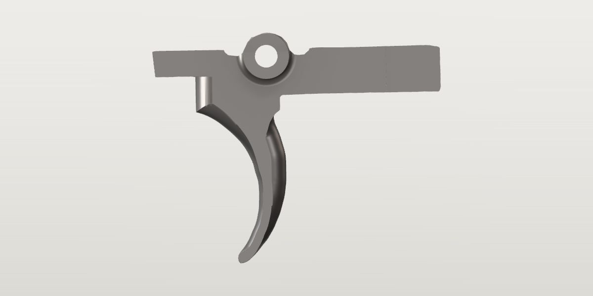
BCM's mil-spec-pattern single-stage trigger group: the PNT (Polished - Nickel - Teflon) trigger and hammer, "a precision machined Mil-Spec AISI8620 investment casting per the USGI TDP (Mil-Spec) for M16/M4 family of weapons", the BCM disconnector and "our impact resistant trigger and hammer pins" (BCM's page). BCM's text names no springs; its exploded drawing and photos show the hammer, trigger and disconnector springs, its parts-kit list names all three beside the PNT trigger and hammer, and T.REX ("including springs and trigger pins") and Alexander's say they are in the assembly. BCM states no pull weight: Primary Arms and AR15Discounts give 5.5 lb, Alexander's about 6. Sellers call it single stage with a curved bow.
- Weight
- No weight on file yet: Not sourced: BCM states none (its page, its marketing site, its brochure; its shop's own product data has "weight":null). What sellers print is the parcel's: MidwayUSA "shippingWeight":0.266159 ("0.266 Pounds", 4.26 oz, in its page's data), AR15Discounts "Weight 4 oz" beside "Dimensions 5.25 × 2 × 2 in" (a box), KYGUNCO "Weight 2 lb" (the figure its other BCM pages carry). None is the part's, so none is entered: the build's weight says it is unknown. A reviewer's scale reading of the assembly, or of a mil-spec trigger group, would close it.
- Lowest price
- $65.95 at BCM, read Nov 21, 2026
- Maker's number
- BCM-PNT-TA1
- Colour
- BCM PNT electroless nickel
- Drawn as
- modelled
- Maker's page
- bravocompanyusa.com
In “BCM 16 in mid-length”, a build on the start page, as it is.
Its figures
Every figure the site draws and checks it by, with where it came from. Open one for each source's reading, and why one is used where they differ.
Weight (the assembly)No value yetMissingNo source yet
Not sourced: BCM states none (its page, its marketing site, its brochure; its shop's own product data has "weight":null). What sellers print is the parcel's: MidwayUSA "shippingWeight":0.266159 ("0.266 Pounds", 4.26 oz, in its page's data), AR15Discounts "Weight 4 oz" beside "Dimensions 5.25 × 2 × 2 in" (a box), KYGUNCO "Weight 2 lb" (the figure its other BCM pages carry). None is the part's, so none is entered: the build's weight says it is unknown. A reviewer's scale reading of the assembly, or of a mil-spec trigger group, would close it.
Trigger and hammer pin diameter (small .154 or large .170)0.154 in ± 0.00025 in 3.9 mmConflictStandard: US Army TDP drawing 8448609 (Pin, Hammer & Trigger), rev H, scale 4/1: the end view; user-supplied scan (Distribution Statement F, Colt proprietary notice), PDF page 73 (a copy on file, never committed)
Standard “Ø.154-.0005” used
US Army TDP drawing 8448609 (Pin, Hammer & Trigger), rev H, scale 4/1: the end view; user-supplied scan (Distribution Statement F, Colt proprietary notice), PDF page 73 (a copy on file, never committed), from the site owner
The middle of .1535 to .1540. The same sheet: .900 long, two grooves (.030R X .125 DIA) at .130 and .450 from one end.
Published “Pin Size: .156" / .157" (small pin)”
Alexander's Store, BCM PNT Trigger Assembly AR-15, Key Specifications (the store's own list), a seller, read Oct 5, 2026 the page, harvested Oct 5, 2026
The same page's prose: "The .156/.157 pin holes are honed for tight alignment" and "uses standard small .156/.157 pins". BCM's sentence, which it restates, is about the holes.
A .156 pin doesn't pass a .156 hole: the store's figure is BCM's for the holes ("156/157 holes are honed"), given as the pin's. The pin a receiver built to the TDP takes is the Army drawing's, and BCM grinds its pins to fit those receivers.
tdp and alexanders differ by 0.003 in beyond what each states it is good to.
BCM gives no diameter for the two pins the assembly comes with: "This assembly includes our impact resistant trigger and hammer pins. They are centerless ground to a fine finish and superior tolerances to ensure compatibility with all MIL SPEC lower receivers built per the USGI TDP." The figure is the Army drawing's for the pin those receivers take (their holes .1560 +.0015, std.ar15.fcg_pin_hole_d); BCM's exploded line drawing shows both pins with that drawing's two grooves. BCM's own number is for the holes the pins pass through (pivot_hole_d), which one seller prints as the pin's.
The trigger's pivot hole (the bore its pin passes through), diameter0.157 in ± 0.0005 in 4 mmConfirmedPublished: Bravo Company USA, BCM® PNT Trigger Assembly AR15 (BCM-PNT-TA1), Description, the maker, read Oct 5, 2026
Published “156/157 holes are honed to assist in perfect alignment and a smooth trigger pull.” used
Bravo Company USA, BCM® PNT Trigger Assembly AR15 (BCM-PNT-TA1), Description, the maker, read Oct 5, 2026 the page, harvested Oct 5, 2026
BCM's shorthand for .156 to .157 in, of the trigger's and the hammer's holes (its marketing site: "trigger and hammer bores are honed to perfection").
Standard “.156 DIA+.002 THRU (BOTH SIDES)”
US Army TDP drawing 8448592 (Trigger), rev L, scale 2/1, sheet 1 of 1; user-supplied scan (Distribution Statement F, Colt proprietary notice), PDF page 43 (a copy on file), from the site owner
View E-E, datum -A-: .156 to .158 through both walls and bosses.
The maker's own figure for this product. It lies inside the Army drawing's .156 to .158: the one dimension BCM states, and it is the drawing's.
The trigger at rest: how far it is turned about its pin from the Army drawing's side elevation (positive turns the blade forward)-1° ± 0.8°ProvisionalWorked out: {aero-m4e1-lower.trigger_rest_angle}
Worked out -1 deg used
{aero-m4e1-lower.trigger_rest_angle}, harvested
No picture of BCM's shows this trigger installed square to the side (its two are lifestyle photos, from above and from below). A trigger of the same drawing at rest in a mil-spec lower is on file: Aero's complete lower (its "Mil-spec Lower Parts Kit"), where the drawing's outline was fitted to the blade in Aero's pin-framed photo. The drawing's elevation has the tail level; no drawing on file shows the trigger against the hammer and disconnector.
The tail's end at rest, X in the trigger's frame (the pin's axis the origin)-1.202 in ± 0.0075 in -30.5 mmProvisionalWorked out: -{std.ar15.trigger_tail_behind_pivot} * cos({.rest_angle})
Worked out -1.2023 in used
-{std.ar15.trigger_tail_behind_pivot} * cos({.rest_angle}), from the site owner
Where the drawing's 1.210 -.015 tail end goes when the trigger is turned to rest: the second point of the frame the side elevation is traced in.
The tail's end at rest, Y in the trigger's frame0.021 in ± 0.017 in 0.5 mmProvisionalWorked out: -{std.ar15.trigger_tail_behind_pivot} * sin({.rest_angle})
Worked out 0.021 in used
-{std.ar15.trigger_tail_behind_pivot} * sin({.rest_angle}), from the site owner
The blade's face ahead of the trigger pin, at rest (the deepest point of its curve)0.05 in ± 0.02 in 1.3 mmProvisionalPhoto: US Army TDP drawing 8448592 (Trigger) rev L (the user's M16 TDP scan, PDF page 43): the side elevation
Photo 0.05 in ± 0.02 in used
US Army TDP drawing 8448592 (Trigger) rev L (the user's M16 TDP scan, PDF page 43): the side elevation, from the site owner
Scale: frame from the reviewed holes pivot, tail (315.2 px/in, rms 0.000 in over 2 points). Read by x_max in x [-0.05, 0.3] in y [-1.05, -0.99] of the traced outline (tools/trace.py); the blade's front edge where it is furthest back, 0.99 to 1.05 below the pin with the trigger at rest (the edge is within 0.001 of that from 0.9 to 1.05; the section line's crossing at 0.95 is left out); ± mostly the rest angle's 0.8° at an inch from the pin (0.014), and the drawing's stroke
Where a finger lies: the front edge's rearmost point, as length of pull is read on the Aero lower's trigger of the same drawing (aero-m4e1-lower.trigger_face_x, 1.964 on its photo against 1.978 by the drawing). The drawing's face is an arc (.62 R about a centre .69 ahead of and .97 below the pivot), which puts its deepest point .07 ahead of the pin before the turn to rest.
The blade's face ahead of the takedown pin on a mil-spec lower (derived)1.978 in ± 0.02 in 50.2 mmProvisionalWorked out: {std.ar15.trigger_pin_x} + {.face_offset_x}
Worked out 1.978 in used
{std.ar15.trigger_pin_x} + {.face_offset_x}, from the site owner
Length of pull is read from here.
The blade's width (Z)0.29 in ± 0.005 in 7.4 mmConfirmedWorked out: {std.ar15.trigger_body_width}
Worked out 0.29 in used
{std.ar15.trigger_body_width}, from the site owner
The blade is as wide as the body: the drawing's front view (unlabelled, over View E-E) and Section A-A draw it between the body's own lines from the bosses to its tip, and the body is .290 -B-. Sellers of mil-spec triggers measure the bow the same (RECOIL's guide: Stag's "measured 0.29 inches wide"; ALG "Bow Width: 0.29"": quoted in larue-mbt-2s.shoe_width).
The bosses round the pivot hole, end to end (across the trigger)0.68 in ± 0.003 in 17.3 mmConflictStandard: US Army TDP drawing 8448592 (Trigger), rev L, scale 2/1, sheet 1 of 1; user-supplied scan (Distribution Statement F, Colt proprietary notice), PDF page 43 (a copy on file)
Standard “.680±.003, symmetrical about -B- within .006 TOTAL” used
US Army TDP drawing 8448592 (Trigger), rev L, scale 2/1, sheet 1 of 1; user-supplied scan (Distribution Statement F, Colt proprietary notice), PDF page 43 (a copy on file), from the site owner
The front view over View E-E (zone 2-D): the callout's extension lines stand on the two bosses' end faces, 214 px apart at the sheet's 315 px/in (0.679). The lower's pocket is .690 wide (std.ar15.fcg_pocket_width).
Worked out 0.664 in
{std.ar15.trigger_boss_length}, from the site owner
The CAD reference set's trigger (a third-party model), as the standard ledger records it.
The drawing dimensions it; beside the TDP the drawing wins and the difference is said: the third-party model's bosses are 0.016 short.
tdp and model differ by 0.016 in beyond what each states it is good to.
The standard ledger has only the reference model's figure here and says the drawing doesn't dimension it; it does, on the unlabelled front view over View E-E. Reported to the catalog's keeper for std.ar15.trigger_boss_length.
The bosses' ends, how far in from each end their upper half is cut away0.058 in ± 0.005 in 1.5 mmConfirmedStandard: US Army TDP drawing 8448592 (Trigger), rev L, scale 2/1, sheet 1 of 1; user-supplied scan (Distribution Statement F, Colt proprietary notice), PDF page 43 (a copy on file)
Standard “.058, 2 PLACES” used
US Army TDP drawing 8448592 (Trigger), rev L, scale 2/1, sheet 1 of 1; user-supplied scan (Distribution Statement F, Colt proprietary notice), PDF page 43 (a copy on file), from the site owner
The front view over View E-E: from each boss's end face to the upper half's (19 px, 0.060). The rear view has the same step (22 px).
Each boss's end is a half round: above a flat just over the pin's axis it stops short. The hammer spring's legs lie on the trigger pin there. Primary Arms' side photo shows it: the lower half ring standing proud round the pin, a line across just above the pin's middle; BCM's exploded drawing draws the same step.
The bosses' ends, the step's flat above the pivot's axis0.03 in ± 0.01 in 0.8 mmConfirmedStandard: US Army TDP drawing 8448592 (Trigger), rev L, scale 2/1, sheet 1 of 1; user-supplied scan (Distribution Statement F, Colt proprietary notice), PDF page 43 (a copy on file)
Standard “.03, 2 PLACES” used
US Army TDP drawing 8448592 (Trigger), rev L, scale 2/1, sheet 1 of 1; user-supplied scan (Distribution Statement F, Colt proprietary notice), PDF page 43 (a copy on file), from the site owner
The front view over View E-E: from the pivot's centre line to the step's line. The rear view puts it 8 px (0.025) above the axis.
The fillet where each boss meets the body's side, radius0.055 in ± 0.015 in 1.4 mmConfirmedStandard: US Army TDP drawing 8448592 (Trigger), rev L, scale 2/1, sheet 1 of 1; user-supplied scan (Distribution Statement F, Colt proprietary notice), PDF page 43 (a copy on file)
Standard “.055 R±.015, 2 PLACES AROUND BOSSES” used
US Army TDP drawing 8448592 (Trigger), rev L, scale 2/1, sheet 1 of 1; user-supplied scan (Distribution Statement F, Colt proprietary notice), PDF page 43 (a copy on file), from the site owner
Section B-B (through the pivot, looking down).
The disconnector's slot, width0.126 in ± 0.0035 in 3.2 mmConfirmedStandard: US Army TDP drawing 8448592 (Trigger), rev L, scale 2/1, sheet 1 of 1; user-supplied scan (Distribution Statement F, Colt proprietary notice), PDF page 43 (a copy on file)
Standard “.122+.007, symmetrical about -B- within .006 TOTAL” used
US Army TDP drawing 8448592 (Trigger), rev L, scale 2/1, sheet 1 of 1; user-supplied scan (Distribution Statement F, Colt proprietary notice), PDF page 43 (a copy on file), from the site owner
The rear view: the middle of .122 to .129. Section A-A gives the same slot as .125 between two .082 walls (.082 + .125 + .082 = .289).
The disconnector's slot, its floor below the pivot's axis0.19 in ± 0.005 in 4.8 mmConfirmedStandard: US Army TDP drawing 8448592 (Trigger), rev L, scale 2/1, sheet 1 of 1; user-supplied scan (Distribution Statement F, Colt proprietary notice), PDF page 43 (a copy on file)
Standard “.190” used
US Army TDP drawing 8448592 (Trigger), rev L, scale 2/1, sheet 1 of 1; user-supplied scan (Distribution Statement F, Colt proprietary notice), PDF page 43 (a copy on file), from the site owner
The side elevation, a section on the centre plane (the hatched strip is the floor): from the pivot's centre line down to the hatching's top, 60 px (0.190). The same chain: .058 ± .002 up to the tail's top, .230 to the spring hole's floor, .270 to the tail's underside.
The disconnector's slot, where its floor runs out at the top ahead of the pivot0.48 in ± 0.01 in 12.2 mmConfirmedStandard: US Army TDP drawing 8448592 (Trigger), rev L, scale 2/1, sheet 1 of 1; user-supplied scan (Distribution Statement F, Colt proprietary notice), PDF page 43 (a copy on file)
Standard “.48” used
US Army TDP drawing 8448592 (Trigger), rev L, scale 2/1, sheet 1 of 1; user-supplied scan (Distribution Statement F, Colt proprietary notice), PDF page 43 (a copy on file), from the site owner
The side elevation: from the pivot's centre line to an extension line standing on the nose's top where the 1.00 R arc reaches it (149 px, 0.473). The top view's slot ends there (0.48).
The disconnector's slot, the radius its floor rises on to the top1 in ± 0.01 in 25.4 mmConfirmedStandard: US Army TDP drawing 8448592 (Trigger), rev L, scale 2/1, sheet 1 of 1; user-supplied scan (Distribution Statement F, Colt proprietary notice), PDF page 43 (a copy on file)
Standard “1.00 R” used
US Army TDP drawing 8448592 (Trigger), rev L, scale 2/1, sheet 1 of 1; user-supplied scan (Distribution Statement F, Colt proprietary notice), PDF page 43 (a copy on file), from the site owner
The side elevation: the arc from the floor up through the nose's top, its centre mark .8 above the pivot (the cutter's path). Its lowest point scales 0.20 below the pivot, the floor's .190.
The disconnector spring's hole in the slot's floor, diameter0.164 in ± 0.004 in 4.2 mmConfirmedStandard: US Army TDP drawing 8448592 (Trigger), rev L, scale 2/1, sheet 1 of 1; user-supplied scan (Distribution Statement F, Colt proprietary notice), PDF page 43 (a copy on file)
Standard “.164 DIA±.004 TO DEPTH SHOWN” used
US Army TDP drawing 8448592 (Trigger), rev L, scale 2/1, sheet 1 of 1; user-supplied scan (Distribution Statement F, Colt proprietary notice), PDF page 43 (a copy on file), from the site owner
The top view; View C (scale 10/1) repeats it as .164 DIA REF.
The disconnector spring's hole, its centre behind the pivot0.614 in ± 0.005 in 15.6 mmConfirmedStandard: US Army TDP drawing 8448592 (Trigger), rev L, scale 2/1, sheet 1 of 1; user-supplied scan (Distribution Statement F, Colt proprietary notice), PDF page 43 (a copy on file)
Standard “.614” used
US Army TDP drawing 8448592 (Trigger), rev L, scale 2/1, sheet 1 of 1; user-supplied scan (Distribution Statement F, Colt proprietary notice), PDF page 43 (a copy on file), from the site owner
The top view: from the pivot's axis back to the hole's centre.
The disconnector spring's hole, its floor below the pivot's axis0.23 in ± 0.005 in 5.8 mmConfirmedStandard: US Army TDP drawing 8448592 (Trigger), rev L, scale 2/1, sheet 1 of 1; user-supplied scan (Distribution Statement F, Colt proprietary notice), PDF page 43 (a copy on file)
Standard “.230 (side elevation); .230 REF (View C)” used
US Army TDP drawing 8448592 (Trigger), rev L, scale 2/1, sheet 1 of 1; user-supplied scan (Distribution Statement F, Colt proprietary notice), PDF page 43 (a copy on file), from the site owner
From the pivot's centre line, on the same chain as the slot's floor (.190) and the tail's underside (.270): the hole is .040 into the floor, .040 short of the underside.
The tail's narrower rear end, its length0.375 in ± 0.015 in 9.5 mmConfirmedStandard: US Army TDP drawing 8448592 (Trigger), rev L, scale 2/1, sheet 1 of 1; user-supplied scan (Distribution Statement F, Colt proprietary notice), PDF page 43 (a copy on file)
Standard “.375±.015, 2 PLACES” used
US Army TDP drawing 8448592 (Trigger), rev L, scale 2/1, sheet 1 of 1; user-supplied scan (Distribution Statement F, Colt proprietary notice), PDF page 43 (a copy on file), from the site owner
Section A-A: from the tail's end forward to the step, each side (117 px, 0.371). The top view has the step 0.85 behind the pivot.
The last of the tail is narrower on both sides. Both BCM side photos show the step as a line across the tail: 145 px from the end in Primary Arms' (0.377 at the 385 px/in its tail gives), 85 px in BCM's own (0.39 at 216).
The tail's narrower rear end, how far each side stands in0.013 in ± 0.003 in 0.3 mmConfirmedStandard: US Army TDP drawing 8448592 (Trigger), rev L, scale 2/1, sheet 1 of 1; user-supplied scan (Distribution Statement F, Colt proprietary notice), PDF page 43 (a copy on file)
Standard “.013±.003, 2 PLACES” used
US Army TDP drawing 8448592 (Trigger), rev L, scale 2/1, sheet 1 of 1; user-supplied scan (Distribution Statement F, Colt proprietary notice), PDF page 43 (a copy on file), from the site owner
Section A-A: between the body's side and the rear end's, each side.
The blade's face, the radius it is rounded on from side to side0.375 in ± 0.015 in 9.5 mmConfirmedStandard: US Army TDP drawing 8448592 (Trigger), rev L, scale 2/1, sheet 1 of 1; user-supplied scan (Distribution Statement F, Colt proprietary notice), PDF page 43 (a copy on file)
Standard “.375 R±.015” used
US Army TDP drawing 8448592 (Trigger), rev L, scale 2/1, sheet 1 of 1; user-supplied scan (Distribution Statement F, Colt proprietary notice), PDF page 43 (a copy on file), from the site owner
Section A-A (through the blade .97 below the pivot, looking up): the hatched section's front, an arc about a centre on the centre plane .375 behind the face; the arc drawn on round under the body passes through that centre's .375. Across the .290 it falls back 0.029 at each side. (Its second callout in that view, .375±.015 2 PLACES, is the tail's step.)
The blade's section in Section A-A, front to back0.194 in ± 0.013 in 4.9 mmProvisionalPhoto: US Army TDP drawing 8448592 (Trigger) rev L, the user's M16 TDP scan, PDF page 43: Section A-A
Photo 0.194 in ± 0.013 in used
US Army TDP drawing 8448592 (Trigger) rev L, the user's M16 TDP scan, PDF page 43: Section A-A, from the site owner
Scale: the body's .290 (-B-) in the same section, 92 px between its two sides' strokes: 317 px/in. Read by the hatched section's rear apex (u 3013) to its front apex (u 3074): 61 px; ± 4 px of a 5 px stroke on a 1-bit scan
The side elevation's blade at that height is 0.18 through (the traced outline): the same within the strokes.
The blade's back, how deep its rounding is in Section A-A0.107 in ± 0.013 in 2.7 mmProvisionalPhoto: US Army TDP drawing 8448592 (Trigger) rev L, the user's M16 TDP scan, PDF page 43: Section A-A
Photo 0.107 in ± 0.013 in used
US Army TDP drawing 8448592 (Trigger) rev L, the user's M16 TDP scan, PDF page 43: Section A-A, from the site owner
Scale: the body's .290 (-B-) in the same section, 92 px between its two sides' strokes: 317 px/in. Read by the hatched section's rear apex (u 3013) to where its outline reaches the body's sides (u 3047, both sides): 34 px; ± 4 px. An arc through those three points has a radius of 0.148, half the width: nearly a full round
The drawing gives the back no radius: the section draws it round from the full width to its rear apex. What is left between this and the face's fall is the flank at the full width, 0.058 (0.194 - 0.107 - 0.029). The side elevation says the same another way: an inner arc on the blade (.71 R, about the centre of the face's .62 R) runs .09 behind the face, where the flank ends (0.194 - 0.107 = 0.087). Primary Arms' side photo shows that line on the blade, about half way through it.
Where the sweep from the block leaves the blade's face, below the pivot's axis0.75 in ± 0.03 in 19 mmProvisionalPhoto: US Army TDP drawing 8448592 (Trigger) rev L, the user's M16 TDP scan, PDF page 43: the side elevation
Photo 0.75 in ± 0.03 in used
US Army TDP drawing 8448592 (Trigger) rev L, the user's M16 TDP scan, PDF page 43: the side elevation, from the site owner
Scale: the elevation's own frame: the pivot at (3051, 2877), 315.2 px/in by the tail's 1.210 -.015. Read by where the blade's inner line and its outer silhouette part, v 3105 to 3120 (the .71 R leader's arrowhead lies across the two there): 0.72 to 0.77 below the pivot's centre line
Below this the blade's silhouette is its face; above it the silhouette runs forward to the block's corner while the flank's own front line goes straight up to the block. The model's prow begins here.
Edges and corners left as cast, radius0.031 in ± 0.005 in 0.8 mmConfirmedStandard: US Army TDP drawing 8448592 (Trigger), rev L, scale 2/1, sheet 1 of 1; user-supplied scan (Distribution Statement F, Colt proprietary notice), PDF page 43 (a copy on file)
Standard “FILLET, EDGE AND CORNER RADII .031, UNLESS OTHERWISE SPECIFIED.” used
US Army TDP drawing 8448592 (Trigger), rev L, scale 2/1, sheet 1 of 1; user-supplied scan (Distribution Statement F, Colt proprietary notice), PDF page 43 (a copy on file), from the site owner
Note 3. Machined edges are broken .010 at most (note 11).
The tail's top above the pivot's axis0.058 in ± 0.002 in 1.5 mmConfirmedStandard: US Army TDP drawing 8448592 (Trigger), rev L, scale 2/1, sheet 1 of 1; user-supplied scan (Distribution Statement F, Colt proprietary notice), PDF page 43 (a copy on file)
Standard “.058±.002, SEE NOTE 7” used
US Army TDP drawing 8448592 (Trigger), rev L, scale 2/1, sheet 1 of 1; user-supplied scan (Distribution Statement F, Colt proprietary notice), PDF page 43 (a copy on file), from the site owner
The side elevation: from the pivot's centre line up to the tail's top (18 px, 0.057). A check on the traced outline.
The tail's underside below the pivot's axis0.27 in ± 0.005 in 6.9 mmConfirmedStandard: US Army TDP drawing 8448592 (Trigger), rev L, scale 2/1, sheet 1 of 1; user-supplied scan (Distribution Statement F, Colt proprietary notice), PDF page 43 (a copy on file)
Standard “.270” used
US Army TDP drawing 8448592 (Trigger), rev L, scale 2/1, sheet 1 of 1; user-supplied scan (Distribution Statement F, Colt proprietary notice), PDF page 43 (a copy on file), from the site owner
The side elevation: from the pivot's centre line down to the tail's underside (85 px, 0.270); View E-E repeats it (.270, 4 PLACES). A check on the traced outline.
The block under the body ahead of the blade, its underside below the pivot's axis (-D-)0.378 in ± 0.007 in 9.6 mmConfirmedStandard: US Army TDP drawing 8448592 (Trigger), rev L, scale 2/1, sheet 1 of 1; user-supplied scan (Distribution Statement F, Colt proprietary notice), PDF page 43 (a copy on file)
Standard “.378±.007 -D-” used
US Army TDP drawing 8448592 (Trigger), rev L, scale 2/1, sheet 1 of 1; user-supplied scan (Distribution Statement F, Colt proprietary notice), PDF page 43 (a copy on file), from the site owner
The side elevation: from the pivot's centre line down to the block's underside (120 px, 0.381). A check on the traced outline.
The block under the body, its front ahead of the pivot0.5 in ± 0.005 in 12.7 mmConfirmedStandard: US Army TDP drawing 8448592 (Trigger), rev L, scale 2/1, sheet 1 of 1; user-supplied scan (Distribution Statement F, Colt proprietary notice), PDF page 43 (a copy on file)
Standard “.500” used
US Army TDP drawing 8448592 (Trigger), rev L, scale 2/1, sheet 1 of 1; user-supplied scan (Distribution Statement F, Colt proprietary notice), PDF page 43 (a copy on file), from the site owner
The side elevation: from the pivot's centre line forward to the block's front face (157 px, 0.498). Section A-A draws that end as a full round across the body's width (".005 MAX FLASH ON THIS RADIUS PERMISSIBLE"), its apex 0.495 ahead. A check on the traced outline.
What it goes with
By the way it mounts, and the figures each part on file states: a part whose figures say it doesn't fit is left out, and one whose fit can't be checked from what is published is marked. A check is against published figures, not a guarantee.
AR-15 fire-control group (mounting only)
- Lower receivers
- Aero Precision M4E1 complete lower, A2 grip and M4 stock, Aero Precision M4E1 Stripped Lower Receiver, Battle Arms Development Workhorse stripped lower, BCM MK2 AR-15 Lower Receiver, Bear Creek Arsenal BC-15 Multi Caliber, Lower Receiver, Black Anodized, Geissele Automatics Super Duty AR-15 Lower Receiver - Stripped Lower, Palmetto State Armory AR-15 "Stealth" Stripped Lower Receiver
Prices on file
Each seller's latest reading of its own page: before tax and shipping, and not a quote. The pages are read again every night.
- BCM $65.95 Nov 21, 2026, in stock that day
- Primary Arms $65.95 Nov 21, 2026, in stock that day
- MidwayUSA $65.95 Nov 21, 2026, in stock that day
- T.REX ARMS $65.95 Nov 21, 2026, in stock that day
- KYGUNCO $65.95 Nov 21, 2026, in stock that day
- Alexander's Store $65.95 Nov 18, 2026, in stock that day
- AR15Discounts $65.95 Nov 21, 2026, out of stock that day
- Rifle Supply $69.99 Nov 21, 2026, out of stock that day