Backup sight
Daniel Defense A1.5 Fixed Rear Sight
Daniel Defense's A1.5 fixed rear sight (Rock & Lock): one piece of 6061-T6 aluminium, hard anodized, on a Picatinny rail by one slotted screw into a self-locking insert; the standard A2 flip aperture (0.070 and 0.200 in) with an A1 windage wheel turned by a bullet's tip. Black; Mil-Spec+ Brown and Tornado Grey in the set with the front sight.
- Weight
- 1.7 oz Conflictpublished: Right to Bear, Daniel Defense Rail Mounted Fixed Sight - Rear: Daniel Defense's own description, in the first person, a seller, read Oct 19, 2026Its sources span 1.65 oz to 1.8 oz.
- Lowest price
- $86.60 at Primary Arms, read Nov 21, 2026 (Black)
- Maker's number
- 19-064-11002
- Colours
- Black, Tornado Grey
- Drawn as
- modelled
- Maker's page
- primaryarms.com
In “Aero 5.56 carbine, fitted out”, a build on the start page, in place of its Magpul MBUS Pro Sight – Rear.
Its figures
Every figure the site draws and checks it by, with where it came from. Open one for each source's reading, and why one is used where they differ.
Length along the rail1.38 in 35.1 mmCorroboratedPublished: Wing Tactical, Daniel Defense AR-15 Fixed Iron Sights (the set 19-088-09116; its spec list gives each sight), a seller, read Oct 19, 2026
Published “Length: Front: 1" Rear: 1.38"” used
Wing Tactical, Daniel Defense AR-15 Fixed Iron Sights (the set 19-088-09116; its spec list gives each sight), a seller, read Oct 19, 2026 the page, harvested Oct 19, 2026
Published “Length: 1.38"”
TLO Outdoors, Daniel Defense A1.5 Fixed Rear Sight, Rock & Lock (specifications list; not a seller on file), a seller, read Oct 19, 2026 the page, harvested Oct 19, 2026
Two sellers' rows agree; Wing, a seller on file, first.
The base's two ends: the front face to the rear end over the relief. It sets the scale of the patent's side elevation and its bottom view.
Width1.24 in 31.5 mmCorroboratedPublished: TLO Outdoors, Daniel Defense A1.5 Fixed Rear Sight, Rock & Lock (specifications list; not a seller on file), a seller, read Oct 19, 2026
Published “Width: 1.24"” used
TLO Outdoors, Daniel Defense A1.5 Fixed Rear Sight, Rock & Lock (specifications list; not a seller on file), a seller, read Oct 19, 2026 the page, harvested Oct 19, 2026
Photo 1.256 in ± 0.015 in
US D631,935 S, FIG. 4, the rear view from the breech; the patent office's copy, page 5, 300 dpi, harvested
Scale: the overall height, wall tops (row 609) to the feet (row 2608): 1999 px for daniel-defense-fixed-rear-sight.height_drawn (1105.5 px/in). Read by the base's feet, outer strokes' centres (u 588 and 1977): 1389 px. The ± covers the scale's (the length's last digit) and a design patent's fidelity
The published figure; the patent's base agrees within 1.3%.
TLO doesn't say what its width spans. The patent's rear elevation, at the scale its overall height gives, has the base's flared feet 1.256 in across, the clamp screw's head 0.039 in further out on the right (1.295 overall) and the drum's hub 1.247 from the left foot: TLO's 1.24 is the base's (or the hub's) width, not the screw head's.
Height, the clamp's lowest edge to the tower's top (a fixed sight: its height)1.78 in 45.2 mmProvisionalPublished: TLO Outdoors, Daniel Defense A1.5 Fixed Rear Sight, Rock & Lock (specifications list; not a seller on file), a seller, read Oct 19, 2026
Published “Height: 1.78"” used
TLO Outdoors, Daniel Defense A1.5 Fixed Rear Sight, Rock & Lock (specifications list; not a seller on file), a seller, read Oct 19, 2026 the page, harvested Oct 19, 2026
TLO's figure, read as the sight's whole height (from the jaws' feet, which stand below the rail's top, to the tower walls' top): above the rail the walls stand 1.58 in by the patent, and with the clamp below the rail 1.81. The patent at the length's scale gives 1.808, 1.6% more (height_drawn): TLO's three figures agree with the patent at 1.38 and 1.24 and not quite here.
Height as the patent draws it (the feet to the tower's top), at the length's scale1.806 in ± 0.01 in 45.9 mmProvisionalPhoto: US D631,935 S (Daniel Defense, 'Rear firearm sight'), FIG. 5, the drum side, the muzzle to the viewer's right (the sight's right); the patent office's copy, page 6, 300 dpi
Photo 1.806 in ± 0.01 in used
US D631,935 S (Daniel Defense, 'Rear firearm sight'), FIG. 5, the drum side, the muzzle to the viewer's right (the sight's right); the patent office's copy, page 6, 300 dpi, harvested
Scale: scale from daniel-defense-fixed-rear-sight.length = 1.38 in (x-extent 1453 px → 1052.9 px/in). Read by height of the traced outline (tools/trace.py); the jaws' feet to the tower's top in the drum-side elevation, at the length's scale. ± covers the length's last digit and a design patent's fidelity
What the rear elevation (FIG. 4) and the model are scaled by, so that the side and the end views of the model are one drawing. 0.028 in over TLO's 1.78 (height).
Sight line above the rail's top (the aperture's centre)1.363 in ± 0.02 in 34.6 mmCorroboratedPhoto: US D631,935 S, FIG. 4, the rear view from the breech; the patent office's copy, page 5, 300 dpi
Photo 1.41 in ± 0.03 in
Wing Tactical's photo 55197: the sight end-on from both ends, 1280 px; the right one from behind, the large aperture standing, as in the patent's FIG. 4, harvested
Scale: the sight's own overall height in the same view, the walls' top (row 337) to the feet (row 942), 605 px, for height_drawn (1.808 in); with TLO's 1.78 it reads 1.39. Read by the hole's centre (row 400: its edges at rows 368 and 432 down column 905, columns 860 and 928 along row 391) over the channel's ceiling, where the body's grey ends on the clamp screw's black (row 873, columns 790 to 1000): 473 px, 0.782 of the height. The ± takes in the scale's choice and the far end's parallax in a lens of unknown distance
Photo 1.363 in ± 0.02 in used
US D631,935 S, FIG. 4, the rear view from the breech; the patent office's copy, page 5, 300 dpi, harvested
Scale: the overall height, wall tops (row 609) to the feet (row 2608): 1999 px for daniel-defense-fixed-rear-sight.height_drawn (1105.5 px/in). Read by the aperture hole's centre (rows 741 and 957 down column 1300, columns 1179 and 1395.5 along row 855: centre u 1287, v 849) over the channel's ceiling (row 2356, columns 1000 and 1500): 1507 px. The front view (FIG. 3) has it at 1.351 the same way
The maker's drawing, and it is borne out twice: its front sight's post (US D631,934 S, drawn with the standard post at one setting) has its tip at 1.330 over the rail at the length's scale, so the pair co-witness on the drawings within 0.03 in; and Wing's two "Center Height Over Rail" figures are the patents' post tip (1.36) and this aperture leg's top (1.54). The end-on photo's 1.41 leans on where the channel's ceiling is under the screw's black and on a scale borrowed from the patent; it stays beside it as a conflict. Magpul's MBUS 3 rear has its aperture at 1.42 ("Center of aperture to top of rail: 1.42 in."): Daniel Defense's sights are a lower pair.
The A2 aperture's centre, standing, over the rail's top (the channel's ceiling). No page states it: Midway (Daniel Defense's text) says "The fixed rear sight is of the correct height for proper alignment with an A2 Rifle or M4 "F" Marked Front Sight Base, as well as for co-witnessing with a red dot optic"; TLO and Alexander's "Absolute Cowitness". Wing's "Center Height Over Rail: Front: 1.36" Rear: 1.54"" are the tops of the two sighting pieces as the patents draw them: the front post's tip 1.330 (the front sight's ledger; Wing's 1.36) and this aperture leg's top 1.548 (the patent's centre 1.363 and the leg's top 0.185 over it): recorded under wing_center_height.
Wing's "Center Height Over Rail" for the rear: the aperture leg's top1.54 in 39.1 mmProvisionalPublished: Wing Tactical, Daniel Defense AR-15 Fixed Iron Sights (the set 19-088-09116; its spec list gives each sight), a seller, read Oct 19, 2026
Published “Center Height Over Rail: Front: 1.36" Rear: 1.54"” used
Wing Tactical, Daniel Defense AR-15 Fixed Iron Sights (the set 19-088-09116; its spec list gives each sight), a seller, read Oct 19, 2026 the page, harvested Oct 19, 2026
Kept as the seller wrote it. It is no centre: the patent has the aperture leg's top 1.548 over the rail (its centre 1.363 and the leg's round top 0.185 above it), and the front's "1.36" in the same row is that sight's post tip (its patent draws it at 1.330 at the length's scale). What Wing calls a centre height is the sighting piece's top on each.
The large aperture's hole0.2 in ± 0.0005 in 5.1 mmCorroboratedPublished: Alexander's, Daniel Defense A1.5 Fixed Rear Sight, Key Specifications, a seller, read Oct 19, 2026
Published “Apertures: Small 0.070" / Large 0.200"”
TLO Outdoors, Daniel Defense A1.5 Fixed Rear Sight, Rock & Lock (specifications list; not a seller on file), a seller, read Oct 19, 2026 the page, harvested Oct 19, 2026
Published “Aperture: Dual Aperture (0.070 in and 0.200 in)” used
Alexander's, Daniel Defense A1.5 Fixed Rear Sight, Key Specifications, a seller, read Oct 19, 2026 the page, harvested Oct 19, 2026
Two sellers agree; Alexander's is a seller on file.
The small aperture's hole0.07 in ± 0.0005 in 1.8 mmCorroboratedPublished: Alexander's, Daniel Defense A1.5 Fixed Rear Sight, Key Specifications, a seller, read Oct 19, 2026
Published “Apertures: Small 0.070" / Large 0.200"”
TLO Outdoors, Daniel Defense A1.5 Fixed Rear Sight, Rock & Lock (specifications list; not a seller on file), a seller, read Oct 19, 2026 the page, harvested Oct 19, 2026
Published “Aperture: Dual Aperture (0.070 in and 0.200 in)” used
Alexander's, Daniel Defense A1.5 Fixed Rear Sight, Key Specifications, a seller, read Oct 19, 2026 the page, harvested Oct 19, 2026
Two sellers agree; Alexander's is a seller on file.
Clamp's length along the rail1.38 in 35.1 mmCorroboratedWorked out: {.length}
Worked out 1.38 in used
{.length}, harvested
The base sits on the rail its whole length; its jaws hook under the rail's head from the front face back to the relief, 1.03 in.
Clamp's reach below the rail's top (the jaws' feet)0.228 in ± 0.01 in 5.8 mmProvisionalPhoto: US D631,935 S, FIG. 4, the rear view from the breech; the patent office's copy, page 5, 300 dpi
Photo 0.228 in ± 0.01 in used
US D631,935 S, FIG. 4, the rear view from the breech; the patent office's copy, page 5, 300 dpi, harvested
Scale: the overall height, wall tops (row 609) to the feet (row 2608): 1999 px for daniel-defense-fixed-rear-sight.height_drawn (1105.5 px/in). Read by the channel's ceiling (row 2356) to the feet (row 2608): 252 px. Wing's end-on photo has 0.114 of the height there (0.206 in at the same height)
Base's front face ahead of the clamp's middle (x)0.69 in ± 0.005 in 17.5 mmCorroboratedWorked out: {.length} / 2
Worked out 0.69 in ± 0.005 in used
{.length} / 2, harvested
Where the side and plan profiles' origin (the base's front face) sits in the part frame.
Clamp's bottom in the sight's frame (y, the rail's top is 0)-0.228 in ± 0.01 in -5.8 mmProvisionalWorked out: -{.clamp_below_rail}
Worked out -0.228 in ± 0.01 in used
-{.clamp_below_rail}, harvested
Where the side and end profiles' origin (the feet) sits in the part frame.
Clamp screw's axis behind the front face0.293 in ± 0.01 in 7.4 mmCorroboratedPhoto: US D631,935 S, FIG. 5, the drum side, "the muzzle end of the firearm ... to the viewer's right"; the patent office's copy, page 6, 300 dpi
Photo 0.293 in ± 0.01 in used
US D631,935 S, FIG. 5, the drum side, "the muzzle end of the firearm ... to the viewer's right"; the patent office's copy, page 6, 300 dpi, harvested
Scale: daniel-defense-fixed-rear-sight.length = 1.38 in: the front face (u 1937.5) to the rear end (u 487.5), 1450 px (1050.7 px/in). Read by the screw head's circle (columns 1429 and 1831 along row 2364, rows 2163 and 2568 down column 1628: centre u 1630, v 2366) behind the front face: 307.5 px. The left side (FIG. 6) has the insert's centre 0.30 in behind its front face
Photo 0.285 in ± 0.01 in
Primary Arms 19-064-11002_01, the drum side square on, 2200 px, harvested
Scale: the base's length on row 1000, 662 to 1512 (850 px) for 1.38 in. Read by the screw head's circle (columns 1222 to 1450, rows 1105 to 1322) behind the front face: 176 px
The drawing the model is built from; the maker's photo agrees within 0.01 in.
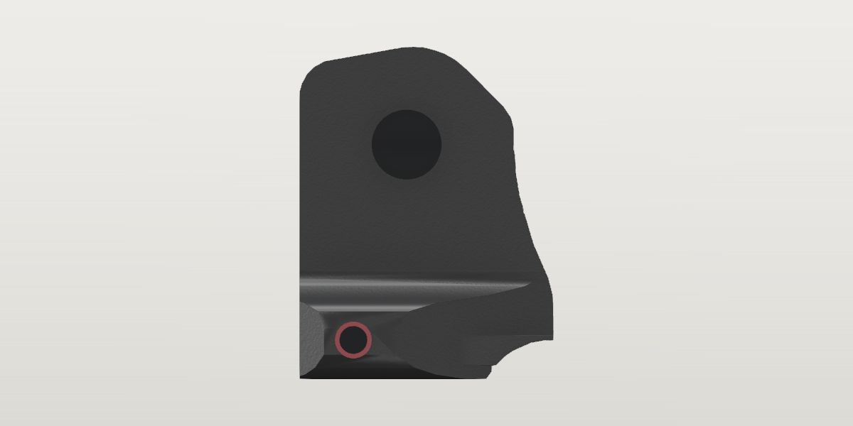
The slotted screw crosses the channel in a groove in its ceiling and lies in a rail slot: it is where the sight is held against a slot. Midway: "attaches easily to any Picatinny-Spec rail with a single slotted screw".
Clamp screw's axis below the rail's top0.015 in ± 0.01 in 0.4 mmProvisionalPhoto: US D631,935 S, FIG. 5, the drum side, "the muzzle end of the firearm ... to the viewer's right"; the patent office's copy, page 6, 300 dpi
Photo 0.015 in ± 0.01 in used
US D631,935 S, FIG. 5, the drum side, "the muzzle end of the firearm ... to the viewer's right"; the patent office's copy, page 6, 300 dpi, harvested
Scale: daniel-defense-fixed-rear-sight.length = 1.38 in: the front face (u 1937.5) to the rear end (u 487.5), 1450 px (1050.7 px/in). Read by the head's centre (v 2366) below the rail's top as the rear view places it over the feet (v 2589.5 less clamp_below_rail: v 2349.9): 16 px
Clamp screw's head0.36 in ± 0.015 in 9.1 mmCorroboratedPhoto: Primary Arms 19-064-11002_01
Photo 0.384 in ± 0.01 in
US D631,935 S, FIG. 5, the drum side, "the muzzle end of the firearm ... to the viewer's right"; the patent office's copy, page 6, 300 dpi, harvested
Scale: daniel-defense-fixed-rear-sight.length = 1.38 in: the front face (u 1937.5) to the rear end (u 487.5), 1450 px (1050.7 px/in). Read by the head's outer circle, 402 px across and 405 px down
Photo 0.36 in ± 0.015 in used
Primary Arms 19-064-11002_01, harvested
Scale: the base's length on row 1000, 850 px for 1.38 in. Read by the head's circle, 228 px across and 217 down
The product as sold: the patent draws the head and its counterbore as one circle.
Clamp screw's head beyond the right foot0.036 in ± 0.006 in 0.9 mmProvisionalPhoto: US D631,935 S, FIG. 4, the rear view from the breech; the patent office's copy, page 5, 300 dpi
Photo 0.036 in ± 0.006 in used
US D631,935 S, FIG. 4, the rear view from the breech; the patent office's copy, page 5, 300 dpi, harvested
Scale: the overall height, wall tops (row 609) to the feet (row 2608): 1999 px for daniel-defense-fixed-rear-sight.height_drawn (1105.5 px/in). Read by the head's outer face (u 2016) beyond the right foot's (u 1977): 39.5 px
Clamp screw's shank0.19 in ± 0.02 in 4.8 mmProvisionalWorked out: An assumption for the drawing, not a reading: no page names the screw. The rear view shows its thread 0.11 in under the ceiling (rows 2356 to 2479) and the side view its axis 0.015 under the rail's top, which makes it about 0.19 across; the sellers' photos show it filling a slot.
Worked out 0.19 in ± 0.02 in used
An assumption for the drawing, not a reading: no page names the screw. The rear view shows its thread 0.11 in under the ceiling (rows 2356 to 2479) and the side view its axis 0.015 under the rail's top, which makes it about 0.19 across; the sellers' photos show it filling a slot., harvested
The screw's thread where it shows under the channel's ceiling, and its axis just under the rail's top: a shank that lies in a rail slot (0.206 in wide).
Tower walls' top above the rail1.58 in ± 0.02 in 40.1 mmProvisionalPhoto: US D631,935 S, FIG. 4, the rear view from the breech; the patent office's copy, page 5, 300 dpi
Photo 1.58 in ± 0.02 in used
US D631,935 S, FIG. 4, the rear view from the breech; the patent office's copy, page 5, 300 dpi, harvested
Scale: the overall height, wall tops (row 609) to the feet (row 2608): 1999 px for daniel-defense-fixed-rear-sight.height_drawn (1105.5 px/in). Read by the walls' top (row 609) over the channel's ceiling (row 2356): 1747 px
Tower walls' thickness0.101 in ± 0.005 in 2.6 mmProvisionalPhoto: US D631,935 S, FIG. 4, the rear view from the breech; the patent office's copy, page 5, 300 dpi
Photo 0.101 in ± 0.005 in used
US D631,935 S, FIG. 4, the rear view from the breech; the patent office's copy, page 5, 300 dpi, harvested
Scale: the overall height, wall tops (row 609) to the feet (row 2608): 1999 px for daniel-defense-fixed-rear-sight.height_drawn (1105.5 px/in). Read by outer to inner face of each wall (u 836 to 947, 1618 to 1732): 111 and 114 px
Body's width at the walls0.81 in ± 0.01 in 20.6 mmProvisionalPhoto: US D631,935 S, FIG. 4, the rear view from the breech; the patent office's copy, page 5, 300 dpi
Photo 0.81 in ± 0.01 in used
US D631,935 S, FIG. 4, the rear view from the breech; the patent office's copy, page 5, 300 dpi, harvested
Scale: the overall height, wall tops (row 609) to the feet (row 2608): 1999 px for daniel-defense-fixed-rear-sight.height_drawn (1105.5 px/in). Read by the walls' outer faces (u 836 and 1732): 896 px
Through-cut window's width0.691 in ± 0.01 in 17.6 mmProvisionalPhoto: US D631,935 S, FIG. 4, the rear view from the breech; the patent office's copy, page 5, 300 dpi
Photo 0.691 in ± 0.01 in used
US D631,935 S, FIG. 4, the rear view from the breech; the patent office's copy, page 5, 300 dpi, harvested
Scale: the overall height, wall tops (row 609) to the feet (row 2608): 1999 px for daniel-defense-fixed-rear-sight.height_drawn (1105.5 px/in). Read by its sides along row 1800 (u 902 and 1666): 764 px
"Through-cut design for weight savings" (Primary Arms): a window through the body from end to end under the aperture, its corners rounded.
Through-cut window's height0.486 in ± 0.01 in 12.3 mmProvisionalPhoto: US D631,935 S, FIG. 4, the rear view from the breech; the patent office's copy, page 5, 300 dpi
Photo 0.486 in ± 0.01 in used
US D631,935 S, FIG. 4, the rear view from the breech; the patent office's copy, page 5, 300 dpi, harvested
Scale: the overall height, wall tops (row 609) to the feet (row 2608): 1999 px for daniel-defense-fixed-rear-sight.height_drawn (1105.5 px/in). Read by its top and bottom down column 1000 (rows 1656 and 2193.5): 537.5 px
Through-cut window's floor above the rail0.147 in ± 0.01 in 3.7 mmProvisionalPhoto: US D631,935 S, FIG. 4, the rear view from the breech; the patent office's copy, page 5, 300 dpi
Photo 0.147 in ± 0.01 in used
US D631,935 S, FIG. 4, the rear view from the breech; the patent office's copy, page 5, 300 dpi, harvested
Scale: the overall height, wall tops (row 609) to the feet (row 2608): 1999 px for daniel-defense-fixed-rear-sight.height_drawn (1105.5 px/in). Read by the window's floor (row 2193.5) over the channel's ceiling (row 2356): 162.5 px
The base's split under the window0.059 in ± 0.006 in 1.5 mmProvisionalPhoto: US D631,935 S, FIG. 4, the rear view from the breech; the patent office's copy, page 5, 300 dpi
Photo 0.059 in ± 0.006 in used
US D631,935 S, FIG. 4, the rear view from the breech; the patent office's copy, page 5, 300 dpi, harvested
Scale: the overall height, wall tops (row 609) to the feet (row 2608): 1999 px for daniel-defense-fixed-rear-sight.height_drawn (1105.5 px/in). Read by the split's walls along row 2250 (u 1252 and 1317): 65 px
The base is split from the window's floor down to the channel (the patent's front and rear views, Wing's end-on photo): the screw draws its two halves onto the rail.
Windage drum's diameter0.74 in ± 0.015 in 18.8 mmCorroboratedPhoto: Primary Arms 19-064-11002_01
Photo 0.761 in ± 0.01 in
US D631,935 S, FIG. 4, the rear view from the breech; the patent office's copy, page 5, 300 dpi, harvested
Scale: the overall height, wall tops (row 609) to the feet (row 2608): 1999 px for daniel-defense-fixed-rear-sight.height_drawn (1105.5 px/in). Read by the disc seen edge on, down column 1760 (rows 778 and 1619): 841 px. The side elevation's outer circle reads 0.782 at its own scale
Photo 0.74 in ± 0.015 in used
Primary Arms 19-064-11002_01, harvested
Scale: the base's length on row 1000, 850 px for 1.38 in. Read by the dark disc, columns 930 to 1394 and rows 344 to 794 (464 and 450 px)
The product as sold, square on; the patent's two views of the disc differ by 0.02 in themselves.
"an A1-Type Windage Wheel that requires a bullet tip or similar tool for adjustment" (Midway): a disc with five holes and the numerals 1 to 5 on the sight's right.
Windage drum's face beyond the right wall0.043 in ± 0.005 in 1.1 mmProvisionalPhoto: US D631,935 S, FIG. 4, the rear view from the breech; the patent office's copy, page 5, 300 dpi
Photo 0.043 in ± 0.005 in used
US D631,935 S, FIG. 4, the rear view from the breech; the patent office's copy, page 5, 300 dpi, harvested
Scale: the overall height, wall tops (row 609) to the feet (row 2608): 1999 px for daniel-defense-fixed-rear-sight.height_drawn (1105.5 px/in). Read by the disc's outer face (u 1779.5) beyond the wall's (u 1732): 47.5 px
Windage drum's centre behind the front face0.582 in ± 0.01 in 14.8 mmCorroboratedPhoto: US D631,935 S, FIG. 5, the drum side, "the muzzle end of the firearm ... to the viewer's right"; the patent office's copy, page 6, 300 dpi
Photo 0.582 in ± 0.01 in used
US D631,935 S, FIG. 5, the drum side, "the muzzle end of the firearm ... to the viewer's right"; the patent office's copy, page 6, 300 dpi, harvested
Scale: daniel-defense-fixed-rear-sight.length = 1.38 in: the front face (u 1937.5) to the rear end (u 487.5), 1450 px (1050.7 px/in). Read by the outer circle's centre (columns 915 and 1737 along row 1253; rows 842.5 and 1664 down column 1320: u 1326, v 1253) behind the front face: 611.5 px
Photo 0.567 in ± 0.012 in
Primary Arms 19-064-11002_01, harvested
Scale: the base's length on row 1000, 850 px for 1.38 in. Read by the disc's centre (u 1162) behind the front face (u 1512): 350 px
The drawing the model is built from; the photo agrees within 0.015 in.
Windage drum's centre above the rail1.047 in ± 0.01 in 26.6 mmProvisionalPhoto: US D631,935 S, FIG. 4, the rear view from the breech; the patent office's copy, page 5, 300 dpi
Photo 1.047 in ± 0.01 in used
US D631,935 S, FIG. 4, the rear view from the breech; the patent office's copy, page 5, 300 dpi, harvested
Scale: the overall height, wall tops (row 609) to the feet (row 2608): 1999 px for daniel-defense-fixed-rear-sight.height_drawn (1105.5 px/in). Read by the disc's middle (row 1198.5) over the channel's ceiling (row 2356): 1157.5 px. The side elevation has 1.044
Drum's hub (the windage screw's head) across0.273 in ± 0.01 in 6.9 mmProvisionalPhoto: US D631,935 S, FIG. 4, the rear view from the breech; the patent office's copy, page 5, 300 dpi
Photo 0.273 in ± 0.01 in used
US D631,935 S, FIG. 4, the rear view from the breech; the patent office's copy, page 5, 300 dpi, harvested
Scale: the overall height, wall tops (row 609) to the feet (row 2608): 1999 px for daniel-defense-fixed-rear-sight.height_drawn (1105.5 px/in). Read by the hub down column 1830 (rows 1048.5 and 1351): 302.5 px. The side elevation's hub circle is 286 px at its scale, 0.272
Drum's hub beyond the right wall0.22 in ± 0.01 in 5.6 mmProvisionalPhoto: US D631,935 S, FIG. 4, the rear view from the breech; the patent office's copy, page 5, 300 dpi
Photo 0.22 in ± 0.01 in used
US D631,935 S, FIG. 4, the rear view from the breech; the patent office's copy, page 5, 300 dpi, harvested
Scale: the overall height, wall tops (row 609) to the feet (row 2608): 1999 px for daniel-defense-fixed-rear-sight.height_drawn (1105.5 px/in). Read by the hub's end (u 1975) beyond the wall's face (u 1732): 243 px
Windage screw's slotted end beyond the left wall0.058 in ± 0.006 in 1.5 mmProvisionalPhoto: US D631,935 S, FIG. 4, the rear view from the breech; the patent office's copy, page 5, 300 dpi
Photo 0.058 in ± 0.006 in used
US D631,935 S, FIG. 4, the rear view from the breech; the patent office's copy, page 5, 300 dpi, harvested
Scale: the overall height, wall tops (row 609) to the feet (row 2608): 1999 px for daniel-defense-fixed-rear-sight.height_drawn (1105.5 px/in). Read by the head's outer face (u 772) beyond the wall's (u 836): 64 px
Windage screw's slotted end across0.38 in ± 0.015 in 9.7 mmProvisionalPhoto: US D631,935 S, FIG. 6, the insert side, the muzzle to the viewer's left; page 7, 300 dpi
Photo 0.38 in ± 0.015 in used
US D631,935 S, FIG. 6, the insert side, the muzzle to the viewer's left; page 7, 300 dpi, harvested
Scale: its own length, the front face (u 528) to the rear end (u 2010), 1482 px for 1.38 in (1074 px/in). Read by the slotted head's outer circle, about 408 px across (u 950 to 1358, v 967 to 1375)
Aperture's standing leg across0.361 in ± 0.01 in 9.2 mmProvisionalPhoto: US D631,935 S, FIG. 4, the rear view from the breech; the patent office's copy, page 5, 300 dpi
Photo 0.361 in ± 0.01 in used
US D631,935 S, FIG. 4, the rear view from the breech; the patent office's copy, page 5, 300 dpi, harvested
Scale: the overall height, wall tops (row 609) to the feet (row 2608): 1999 px for daniel-defense-fixed-rear-sight.height_drawn (1105.5 px/in). Read by the leg's sides along row 855 (u 1082 and 1481.5): 399.5 px. The large hole in it reads 216 px, 0.195 in: the published 0.200 within 2.5%, a check on this view's scale
Aperture leg's top above its hole's centre0.185 in ± 0.01 in 4.7 mmCorroboratedPhoto: US D631,935 S, FIG. 4, the rear view from the breech; the patent office's copy, page 5, 300 dpi
Photo 0.185 in ± 0.01 in used
US D631,935 S, FIG. 4, the rear view from the breech; the patent office's copy, page 5, 300 dpi, harvested
Scale: the overall height, wall tops (row 609) to the feet (row 2608): 1999 px for daniel-defense-fixed-rear-sight.height_drawn (1105.5 px/in). Read by the leg's round top (row 645, column 1300) above the hole's centre (row 849): 204 px
Photo 0.173 in ± 0.01 in
Wing Tactical 55197, the sight from behind, harvested
Scale: the overall height, 605 px for height_drawn (1.808 in). Read by the leg's top (row 342, column 905) above the hole's centre (row 400): 58 px
The drawing the sight line is adopted from; with it the leg's top is 1.548 over the rail, Wing's "Rear: 1.54". The photo's 0.173 stays beside it.
Aperture legs' thickness along the rail0.09 in ± 0.03 in 2.3 mmProvisionalWorked out: An assumption for the drawing, not a reading: the top view (FIG. 7) draws the standing leg about 0.1 in thick along the rail between the windage screw's threads, under hatching that hides its edges; the A2 aperture's own drawing isn't on file.
Worked out 0.09 in ± 0.03 in used
An assumption for the drawing, not a reading: the top view (FIG. 7) draws the standing leg about 0.1 in thick along the rail between the windage screw's threads, under hatching that hides its edges; the A2 aperture's own drawing isn't on file., harvested
The lying aperture leg's reach from the windage screw's axis0.28 in ± 0.05 in 7.1 mmProvisionalWorked out: An assumption for the drawing, not a reading: the top view (FIG. 7) and Primary Arms' three-quarter photos (adc34e7a2d9f, 86d9f645ef0f) show the small aperture's leg lying flat under the standing one, about as long as the standing leg stands above the screw.
Worked out 0.28 in ± 0.05 in used
An assumption for the drawing, not a reading: the top view (FIG. 7) and Primary Arms' three-quarter photos (adc34e7a2d9f, 86d9f645ef0f) show the small aperture's leg lying flat under the standing one, about as long as the standing leg stands above the screw., harvested
Windage drum's holes (for a bullet's tip)0.1 in ± 0.015 in 2.5 mmCorroboratedPhoto: Primary Arms 19-064-11002_01, the drum square on
Photo 0.1 in ± 0.015 in used
Primary Arms 19-064-11002_01, the drum square on, harvested
Scale: the base's length on row 1000, 850 px for 1.38 in. Read by the five dark holes, about 61 px across each
Photo 0.12 in ± 0.015 in
US D631,935 S, FIG. 5, the drum side, "the muzzle end of the firearm ... to the viewer's right"; the patent office's copy, page 6, 300 dpi, harvested
Scale: daniel-defense-fixed-rear-sight.length = 1.38 in: the front face (u 1937.5) to the rear end (u 487.5), 1450 px (1050.7 px/in). Read by the holes' circles, 116 to 133 px across
The product as sold; the patent draws the drum 5% larger too.
Windage drum's holes: the circle their centres lie on0.546 in ± 0.015 in 13.9 mmCorroboratedPhoto: Primary Arms 19-064-11002_01
Photo 0.546 in ± 0.015 in used
Primary Arms 19-064-11002_01, harvested
Scale: the base's length on row 1000, 850 px for 1.38 in. Read by the upper left hole's centre (u 1063, v 433) from the drum's (u 1162, v 569): 168 px, as a radius
Photo 0.548 in ± 0.015 in
US D631,935 S, FIG. 5, the drum side, "the muzzle end of the firearm ... to the viewer's right"; the patent office's copy, page 6, 300 dpi, harvested
Scale: daniel-defense-fixed-rear-sight.length = 1.38 in: the front face (u 1937.5) to the rear end (u 487.5), 1450 px (1050.7 px/in). Read by the holes by the numerals 1 and 3 (centres u 1496 v 1012, u 1325 v 1533) from the drum's centre (u 1326, v 1253): 295 and 280 px, as radii
The product as sold; the two agree.
Thread insert's red rim across0.2 in ± 0.02 in 5.1 mmProvisionalPhoto: Primary Arms 19-064-11002_03, the left side square on
Photo 0.2 in ± 0.02 in used
Primary Arms 19-064-11002_03, the left side square on, harvested
Scale: its framing is _01's (the same 2200 px series, the base 850 px long for 1.38 in). Read by the red ring round the screw's end, about 121 px across
The pocket under the aperture, along the rail0.627 in ± 0.02 in 15.9 mmProvisionalPhoto: US D631,935 S, FIG. 7, the top view; page 8, 300 dpi
Photo 0.627 in ± 0.02 in used
US D631,935 S, FIG. 7, the top view; page 8, 300 dpi, harvested
Scale: its own length, the rear end (u 445.5) to the front face (u 1948), 1502.5 px for 1.38 in (1088.8 px/in). Read by the broken-line rounded rectangle's ends (u 975 and 1658): 683 px; its middle (u 1316.5) 0.58 in behind the front face, over the drum's axis
The top view (FIG. 7) draws a rounded pocket in broken lines under the U's floor round the aperture's foot and the windage screw: hidden, so only its outline is drawn.
The pocket under the aperture, across0.467 in ± 0.02 in 11.9 mmProvisionalPhoto: US D631,935 S, FIG. 7, the top view; page 8, 300 dpi
Photo 0.467 in ± 0.02 in used
US D631,935 S, FIG. 7, the top view; page 8, 300 dpi, harvested
Scale: its own length, 1502.5 px for 1.38 in (1088.8 px/in). Read by the broken-line rounded rectangle's sides (v 1367 and 1875): 508 px
The pocket under the aperture, its depth under the U's floor0.42 in ± 0.08 in 10.7 mmProvisionalWorked out: An assumption for the drawing, not a reading: no view gives the pocket's depth. Taken down to a web over the window's top, which brings the model's metal (6061 at std.density.aluminium, the hardware as std.density.steel) to 1.81 oz, between the maker's 1.7 and Wing's 1.80; without it the model weighs 2.0.
Worked out 0.42 in ± 0.08 in used
An assumption for the drawing, not a reading: no view gives the pocket's depth. Taken down to a web over the window's top, which brings the model's metal (6061 at std.density.aluminium, the hardware as std.density.steel) to 1.81 oz, between the maker's 1.7 and Wing's 1.80; without it the model weighs 2.0., harvested
What it goes with
By the way it mounts, and the figures each part on file states: a part whose figures say it doesn't fit is left out, and one whose fit can't be checked from what is published is marked. A check is against published figures, not a guarantee.
Picatinny rail (MIL-STD-1913)
- Uppers
- Aero Precision M4E1 Enhanced Upper Receiver Stripped, Aero Precision M4E1 Threaded upper receiver, BCM M4 Upper Receiver Assembly (w/ Laser T-Markings), Expo Arms 7075 Stripped AR-15 Upper Receiver, Geissele Automatics Super Duty Stripped Upper Receiver, Nordic Components 22RB .22 LR upper, 16", Palmetto State Armory AR-15 Stripped Upper Receiver, Panzer Arms AR57 ULT Complete AR-15 Upper Receiver - 5.7x28mm - 12", Panzer Arms AR57 Ultra Light Tactical Complete AR-15 Upper Receiver - 5.7x28mm - 16"
- Handguards
- Aero Precision AR15 10.3" R-ONE M-LOK handguard, Aero Precision AR15 12.7" R-ONE M-LOK handguard, Aero Precision AR15 15" Enhanced M-LOK Handguard, Gen 2, Aero Precision AR15 15" R-ONE M-LOK handguard, Aero Precision AR15 15" S-ONE M-LOK Handguard, Aero Precision AR15 16.6" R-ONE M-LOK handguard, Aero Precision AR15 7.3" R-ONE M-LOK handguard, Aero Precision AR15 9.3" R-ONE M-LOK handguard, BCM MCMR-10 (M-LOK® Compatible* Modular Rail), BCM MCMR-13 (M-LOK® Compatible* Modular Rail), BCM MCMR-15 (M-LOK® Compatible* Modular Rail), Expo Arms Free Float AR-15 Handguard - M-LOK - 15", Geissele Automatics 10.5" Super Modular Rail MK16 M-LOK, Geissele Automatics 13.5" Super Modular Rail MK16 M-LOK, Geissele Automatics 15" Super Modular Rail MK16 M-LOK, MAS Defense 12.62" NERO M-LOK FREE FLOAT, MAS Defense 15" NERO M-LOK FREE FLOAT, MAS Defense 9.87" NERO M-LOK FREE FLOAT, Midwest Industries AR-15/M16 Two Piece Drop-In Handguard, M-LOK® (Carbine), Midwest Industries AR-15/M16 Two Piece Drop-In Handguard, M-LOK® (Mid-Length), Midwest Industries Combat Rail One Piece Free Float Handguard, M-LOK™ (15")
- Frames
- Taurus TX22 Gen 2 frame
- Rail sections
- Magpul M-LOK® Aluminum Rail, 3 Slots, Magpul M-LOK® Aluminum Rail, 5 Slots, Magpul M-LOK® Aluminum Rail, 7 Slots, Magpul M-LOK® Aluminum Rail, 9 Slots, Magpul M-LOK® Polymer Rail, 11 Slots, Magpul M-LOK® Polymer Rail, 3 Slots, Magpul M-LOK® Polymer Rail, 5 Slots, Magpul M-LOK® Polymer Rail, 7 Slots, Magpul M-LOK® Polymer Rail, 9 Slots
Sight and magnifier
Prices on file
Each seller's latest reading of its own page: before tax and shipping, and not a quote. The pages are read again every night.
- Primary Arms $86.60 Black Nov 21, 2026, in stock that day
- Right To Bear $105.00 Black Nov 21, 2026, in stock that day
- MidwayUSA $110.00 Black Nov 21, 2026, in stock that day
- Alexander's Store $110.99 Black Nov 18, 2026, in stock that day