Scope mount
Primary Arms SLx Cantilever 30mm Mount - 1.5"
Primary Arms' one-piece cantilever scope mount for a 30 mm tube: "6061 Aluminum construction", "Steel hardware", "Three bolt design for increased strength", "Dual recoil lugs", "1.5" Optical centerline". The scope slides in its two rings before their caps are tightened ("Rings - 16-18 in. lbs."), which sets the eye relief; the clamp's three cross bolts lie in three of the rail's slots ("Base - 30-35 in. lbs.").
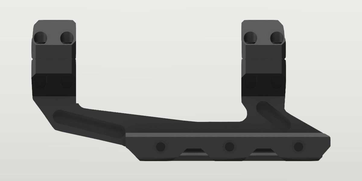
- Weight
- 5.79 oz Confirmedpublished: Primary Arms, SLx Cantilever 30mm Mount - 1.5" (PA-SLX-CM-30-1.5), product page, the maker, read Oct 13, 2026
- Lowest price
- $89.99 at Primary Arms, read Nov 21, 2026 (Black)
- Maker's number
- PA-SLX-CM-30-1.5
- Colour
- Black (placeholder)
- Drawn as
- modelled
- Maker's page
- primaryarms.com
In “22RB carbine, scoped”, a build on the start page, in place of its SIG SAUER ALPHA-MSR scope mount, 30 mm.
Its figures
Every figure the site draws and checks it by, with where it came from. Open one for each source's reading, and why one is used where they differ.
Ring axis above the rail's top1.5 in 38.1 mmConfirmedPublished: Primary Arms, SLx Cantilever 30mm Mount - 1.5" (PA-SLX-CM-30-1.5), product page, the maker, read Oct 13, 2026
Published “1.5" Optical centerline” used
Primary Arms, SLx Cantilever 30mm Mount - 1.5" (PA-SLX-CM-30-1.5), product page, the maker, read Oct 13, 2026 the page, harvested Oct 13, 2026
The page's features list. Its title says the same ("SLx Cantilever 30mm Mount - 1.5""); the item feed's meta text: "features a 1.5in optic height". What it is measured from isn't said: taken, as every maker's centreline height is, from the rail's top.
Tube diameter the rings are bored for1.181 in 30 mmConfirmedPublished: Primary Arms, SLx Cantilever 30mm Mount - 1.5" (PA-SLX-CM-30-1.5), product page, the maker, read Oct 13, 2026
Published “For 30mm scope tubes” used
Primary Arms, SLx Cantilever 30mm Mount - 1.5" (PA-SLX-CM-30-1.5), product page, the maker, read Oct 13, 2026 the page, harvested Oct 13, 2026
The specifications table: "Mount Compatibility 30mm".
The two rings, front face to front face (and middle to middle)3.6 in ± 0.04 in 91.4 mmConflictPhoto: Primary Arms PA-SLX-CM-30-1.5_01.jpg, from the front right and a little above, 2200 x 1488
Photo 3.6 in ± 0.04 in used
Primary Arms PA-SLX-CM-30-1.5_01.jpg, from the front right and a little above, 2200 x 1488, harvested
Scale: ring_bore: the four rims of the two bores, each a 30 mm circle. Read by A pinhole camera (its axis through the picture's middle; distance, focal length, where the bores' axis points and lies, the rings' spacing and their length left free) fitted to the outline of each bore's see-through region against the white background (an arc of the near rim and an arc of the far rim) and to the front ring's near rim found all the way round (303 edge points): 1023 points, rms 1.3 px over the 83% within 3 px (the rest are the split's gap and the far rims' shadowed edge). Two runs: 3.598 and 3.602 in; the lens 25 in off, the axis 46 degrees off the line of sight. The same fit has each bore 0.736 in long rim to rim. The ± is what the lens's axis off the picture's middle by 300 px would move it, and the two runs.
Photo 3.638 in ± 0.04 in
Primary Arms PA-SLX-CM-30-1.5_03.jpg, from the rear left and above, 2200 x 1460, harvested
Scale: ring_bore: the four rims of the two bores, each a 30 mm circle. Read by The same camera fitted to the outlines of the two bores' see-through regions in the other oblique view (no rim found all the way round here): 599 points, rms 1.1 px over the 82% within 3 px; the lens 31 in off, the axis 47.5 degrees off the line of sight; each bore 0.770 in long rim to rim, where the front-right view has 0.736 and the side view has the rings 0.765 face to face. One run. The ± is the first camera's.
Worked out 3.57 in ± 0.02 in
What the rail's pitch would make it: the rings' faces are 3.013 times as far apart as the cross bolts' ends in the left view (1392.8 px for 462.3) and 3.035 times as far apart as their heads in the right view (1199 px for 395.0), and three slots are 1.182 in: 3.56 to 3.59. A clamp's bolts are surely made to the pitch; that these three are three slots apart is itself read at the bores' scale (1.195 in)., harvested
The bores are the one published size that shows, and the first camera is the better fitted of the two (a rim found all the way round as well as the see-through outlines; two runs within 0.004 in). Its figure lies between the other two, and its ± reaches both: the second camera reads 1.1% more, and the rail's pitch under the cross bolts 0.8% less. Every length read at this scale carries that 1%.
camera-rear and slots differ by 0.068 in beyond what each states it is good to.
The length every other reading is scaled by: the only one that comes from the published 30 mm alone. Three readings, 2% from the least to the most: two cameras fitted to the bores in two oblique views, 1.1% apart, and what three rail slots under the cross bolts would make it, 0.8% under the first camera's. The first camera's is between the other two and its ± takes in both.
Rear ring, its middle ahead of the rear cross bolt0.598 in ± 0.02 in 15.2 mmProvisionalPhoto: Primary Arms PA-SLX-CM-30-1.5_02.jpg, left side square on, 2200 x 1467
Photo 0.598 in ± 0.02 in used
Primary Arms PA-SLX-CM-30-1.5_02.jpg, left side square on, 2200 x 1467, harvested
Scale: ring_spacing: the two rings' front faces, 1392.5 px apart at their near edges (columns 118.5 and 1511.0), and their rear faces, 1393.0 (414.4 and 1807.4): 387 px/in at the depth of the rings' near edges. Read by The ring's two end faces at their near edges on rows through its side flat (columns 1511.0 and 1807.4, the lit edge's middle and the silhouette), their middle 1659.2; the rear cross bolt's end at column 1890.8 (the dark recess round each bolt's end, the middle of its extent; the three are 461.8 and 462.8 px apart). The view is level: both rings' top flats on row 266 and both splits on row 525.0. The bolt's end stands about 0.15 in further from the lens than the rings' edges, which is 0.007 in here: inside the ±.
Front ring, its middle ahead of the rear cross bolt4.197 in ± 0.045 in 106.6 mmProvisionalPhoto: Primary Arms PA-SLX-CM-30-1.5_02.jpg, left side square on, 2200 x 1467
Photo 4.197 in ± 0.045 in used
Primary Arms PA-SLX-CM-30-1.5_02.jpg, left side square on, 2200 x 1467, harvested
Scale: ring_spacing (387 px/in at the depth of the rings' near edges). Read by The front ring's two end faces at their near edges (columns 118.5 and 414.4), their middle 266.45; the rear cross bolt's end at column 1890.8. The ± is the scale's 1% over this length.
Each ring's length along the tube (face to face)0.765 in ± 0.012 in 19.4 mmProvisionalPhoto: Primary Arms PA-SLX-CM-30-1.5_02.jpg, left side square on, 2200 x 1467
Photo 0.765 in ± 0.012 in used
Primary Arms PA-SLX-CM-30-1.5_02.jpg, left side square on, 2200 x 1467, harvested
Scale: ring_spacing (387 px/in). Read by Each ring between its end faces' near edges on rows 470 to 600: 295.9 px (front ring) and 296.4 (rear). The camera fitted to the bores in the front-right view has each bore 0.736 in rim to rim: the bores' mouths are broken by about 0.015 in each.
Rings, their top flat above the axis0.669 in ± 0.01 in 17 mmProvisionalPhoto: Primary Arms PA-SLX-CM-30-1.5_02.jpg, left side square on, 2200 x 1467
Photo 0.669 in ± 0.01 in used
Primary Arms PA-SLX-CM-30-1.5_02.jpg, left side square on, 2200 x 1467, harvested
Scale: ring_spacing (387 px/in). Read by Both rings' top flats on row 266 against the split between cap and lower half on row 525.0 (the dark gap, rows 523 to 527, on a column through each ring): 259 px. The split is taken to be at the bore's middle height (the cap is a half ring). The cap is then 0.078 in thick over the tube.
Rings, across their side flats1.53 in ± 0.05 in 38.9 mmProvisionalPhoto: Primary Arms PA-SLX-CM-30-1.5_01.jpg, from the front right and a little above, 2200 x 1488
Photo 1.53 in ± 0.05 in used
Primary Arms PA-SLX-CM-30-1.5_01.jpg, from the front right and a little above, 2200 x 1488, harvested
Scale: ring_bore, through the pinhole camera fitted to the bores' four rims (ring_spacing's source); where each picked point lies along the mount is taken from the left side view. Read by The corner where the split's line on the front ring's right side flat meets the flat's front edge (picked at 1500, 793 on a gridded crop), 0.074 in behind the ring's front face: its line of sight meets that station 0.766 in from the bores' axis, which is half the width. Checked on the three cross bolts' heads, picked the same way at their own stations: they come out 1.503, 1.507 and 1.490 in below the axis (the side view: 1.507) and 0.689, 0.680 and 0.676 in out from it. A pixel is 0.002 in there; 0.02 in of station moves a reading 0.02.
No view is square across the mount: read through the camera fitted to the bores in the front-right view.
Rings, the side flat's upper edge above the axis (where the cap's chamfer begins)0.24 in ± 0.008 in 6.1 mmProvisionalPhoto: Primary Arms PA-SLX-CM-30-1.5_02.jpg, left side square on, 2200 x 1467
Photo 0.24 in ± 0.008 in used
Primary Arms PA-SLX-CM-30-1.5_02.jpg, left side square on, 2200 x 1467, harvested
Scale: ring_spacing (387 px/in). Read by The line between the cap's lit chamfer and its darker side flat, row 432 on both rings, against the split on row 525.0.
Rings, the side flat's lower edge below the axis (where the lower half's chamfer begins)0.25 in ± 0.008 in 6.3 mmProvisionalPhoto: Primary Arms PA-SLX-CM-30-1.5_02.jpg, left side square on, 2200 x 1467
Photo 0.25 in ± 0.008 in used
Primary Arms PA-SLX-CM-30-1.5_02.jpg, left side square on, 2200 x 1467, harvested
Scale: ring_spacing (387 px/in). Read by The line between the lower half's side flat and the chamfer under it, rows 621 to 623 on both rings, against the split on row 525.0.
Rings, the top flat's width across0.672 in ± 0.06 in 17.1 mmProvisionalWorked out: {.ring_width} - 2 * ({.ring_top_above_axis} - {.ring_side_flat_above_axis})
Worked out 0.672 in ± 0.06 in used
{.ring_width} - 2 * ({.ring_top_above_axis} - {.ring_side_flat_above_axis}), harvested
Worked out, not read: the cap's two chamfers taken at 45 degrees between the side flats and the top flat. The cap's real section isn't a plain octagon: from the front right each screw's pair of holes stands on a shoulder flatter than 45 degrees (each hole's mouth is 60 px tall in the side view where a 45 degree face would show 89), under a curve up to the top flat. Not read.
Rings, the chamfer between each side flat and each end face (its length along the tube)0.074 in ± 0.006 in 1.9 mmProvisionalPhoto: Primary Arms PA-SLX-CM-30-1.5_02.jpg, left side square on, 2200 x 1467
Photo 0.074 in ± 0.006 in used
Primary Arms PA-SLX-CM-30-1.5_02.jpg, left side square on, 2200 x 1467, harvested
Scale: ring_spacing (387 px/in). Read by On each ring's near side flat, the line where the flat ends (columns 147 and 385 on the front ring, 1545 and 1780 on the rear) against the end faces' near edges (118.5, 414.4; 1511.0, 1807.4): 27 to 29 px. Drawn at 45 degrees.
Ring cap screws, the two on a side, centre to centre along the tube0.453 in ± 0.006 in 11.5 mmProvisionalPhoto: Primary Arms PA-SLX-CM-30-1.5_02.jpg, left side square on, 2200 x 1467
Photo 0.453 in ± 0.006 in used
Primary Arms PA-SLX-CM-30-1.5_02.jpg, left side square on, 2200 x 1467, harvested
Scale: ring_spacing (387 px/in). Read by Where the picture round one hole is found again at the other (normalised correlation of a 111 px patch): 177.0 px on the front ring, 173.8 on the rear.
Ring cap screws, the hole each sits in (its diameter)0.23 in ± 0.01 in 5.8 mmProvisionalPhoto: Primary Arms PA-SLX-CM-30-1.5_02.jpg, left side square on, 2200 x 1467
Photo 0.23 in ± 0.01 in used
Primary Arms PA-SLX-CM-30-1.5_02.jpg, left side square on, 2200 x 1467, harvested
Scale: ring_spacing (387 px/in). Read by Each hole's width along the tube on a row through it, 87 to 90 px (131 to 221 and 311 to 398 on the front ring). The holes go straight down through the cap's chamfer, so each shows as an ellipse 60 px tall.
Ring cap screws, the hole's middle above the axis as the side sees it0.333 in ± 0.01 in 8.5 mmProvisionalPhoto: Primary Arms PA-SLX-CM-30-1.5_02.jpg, left side square on, 2200 x 1467
Photo 0.333 in ± 0.01 in used
Primary Arms PA-SLX-CM-30-1.5_02.jpg, left side square on, 2200 x 1467, harvested
Scale: ring_spacing (387 px/in). Read by Each hole's ellipse between rows 366 and 425, its middle 396, against the split on row 525.0.
The arm, across (the beam the rings stand on)0.75 in ± 0.07 in 19 mmProvisionalPhoto: Primary Arms PA-SLX-CM-30-1.5_01.jpg, from the front right and a little above, 2200 x 1488
Photo 0.75 in ± 0.07 in used
Primary Arms PA-SLX-CM-30-1.5_01.jpg, from the front right and a little above, 2200 x 1488, harvested
Scale: ring_bore, through the pinhole camera fitted to the bores' four rims (ring_spacing's source). Read by The two ends of the long pocket in the arm's right side (picked at 1545, 1140 and 1185, 1135), each at the station and height the left side view has that end of the left side's pocket: they come out 0.403 and 0.346 in out from the axis's plane, and 0.986 and 1.231 in below the axis where the side view has 0.989 and 1.248. Twice their mean.
A weak reading: two points on one side, the other side taken to mirror it.
The pockets in the arm's sides and under the rear ring, their depth0.19 in ± 0.05 in 4.8 mmProvisionalPhoto: Primary Arms PA-SLX-CM-30-1.5_01.jpg, from the front right and a little above, 2200 x 1488
Photo 0.19 in ± 0.05 in used
Primary Arms PA-SLX-CM-30-1.5_01.jpg, from the front right and a little above, 2200 x 1488, harvested
Scale: ring_bore, through the pinhole camera fitted to the bores' four rims (442 px/in at the front ring, the axis 46 degrees off the line of sight). Read by The wall of the long pocket's rear end as that view shows it, from the pocket's rim (column 1187) to its floor's edge (1245): 58 px across the mount, which that view foreshortens by the sine of 44 degrees. Neither side view shows background through either pocket: they are blind, one in each side, with a web between.
Clamp cross bolts, centre to centre (three bolts, two equal spacings)1.182 in 30 mmConfirmedWorked out: 3 * {std.picatinny.slot_pitch}
Worked out 1.182 in used
3 * {std.picatinny.slot_pitch}, harvested
Photo 1.195 in ± 0.014 in
Primary Arms PA-SLX-CM-30-1.5_02.jpg, left side square on, 2200 x 1467, harvested
Scale: ring_spacing (387 px/in at the rings' near edges; the bolts' ends stand about 0.15 in further off, 0.3%). Read by The dark recess round each bolt's end in the three bosses, the middle of its extent: columns 966.2, 1428.0 and 1890.8 on rows 1107.8, 1108.8 and 1108.0. The right view's three heads are 395.0 px apart each.
The three bolts lie in recoil slots, which are a whole number of pitches apart, and the reading at the bores' own scale is three pitches within its ±: 1.195 against 1.182. A slot's clearance round a 0.16 in bolt would allow either.
Each bolt lies in a recoil slot (Primary Arms: "dual machined recoil lugs and 3 cross bolt lugs"). Their ends read 461.8 and 462.8 px apart in the left view: 1.195 in at the bores' scale, three slots (1.182) within 1.1%, which is that scale's own ±. Here the spacing is the reading and the pitch its check.
Clamp cross bolts, their axis below the rail's top0.007 in ± 0.02 in 0.2 mmProvisionalPhoto: Primary Arms PA-SLX-CM-30-1.5_02.jpg, left side square on, 2200 x 1467
Photo 0.007 in ± 0.02 in used
Primary Arms PA-SLX-CM-30-1.5_02.jpg, left side square on, 2200 x 1467, harvested
Scale: ring_spacing (387 px/in), and optical_axis_above_rail. Read by The bolts' ends on row 1108.2 against the rings' split on row 525.0: 583.2 px, 1.507 in, less the published 1.5. The ± is the scale's 1% over that height and the published figure's last digit isn't in it.
The maker's 1.5 in is to the rail's top; the bolts' axes read 1.507 in below the rings' axis. With the bolt 0.16 in across, its underside is then 0.087 in down a recoil slot 0.118 deep.
Clamp cross bolts, the threaded end's diameter as it shows in the left side's bosses0.16 in ± 0.01 in 4.1 mmProvisionalPhoto: Primary Arms PA-SLX-CM-30-1.5_02.jpg, left side square on, 2200 x 1467
Photo 0.16 in ± 0.01 in used
Primary Arms PA-SLX-CM-30-1.5_02.jpg, left side square on, 2200 x 1467, harvested
Scale: ring_spacing (387 px/in). Read by The bright end of each bolt inside its dark recess, 60 to 64 px across; the recess itself (clamp_bolt_recess_d) 91 px.
Clamp cross bolts, the recess round each bolt's end in the left side's bosses0.235 in ± 0.01 in 6 mmProvisionalPhoto: Primary Arms PA-SLX-CM-30-1.5_02.jpg, left side square on, 2200 x 1467
Photo 0.235 in ± 0.01 in used
Primary Arms PA-SLX-CM-30-1.5_02.jpg, left side square on, 2200 x 1467, harvested
Scale: ring_spacing (387 px/in). Read by The dark ring round each bolt's end, 90 to 92 px across (1382 to 1474 round the middle one).
Clamp cross bolts, the head's diameter (Torx, on the right)0.31 in ± 0.015 in 7.9 mmProvisionalPhoto: Primary Arms PA-SLX-CM-30-1.5_04.jpg, right side from about 6 degrees above, 2200 x 1467
Photo 0.31 in ± 0.015 in used
Primary Arms PA-SLX-CM-30-1.5_04.jpg, right side from about 6 degrees above, 2200 x 1467, harvested
Scale: clamp_bolt_spacing: the three heads 395.0 px apart each (columns 430.5, 825.5, 1220.5), 334 px/in at the clamp bar's face. Read by Each head 104 to 106 px across; the counterbore it sits in 127 to 129 px (clamp_bolt_counterbore_d). This view is from above (the rings' caps read 15% tall against their length, and the screws show at the bottoms of their holes): only what lies in the bar's own face is read on it.
Clamp cross bolts, the counterbore each head sits in (in the clamp bar)0.385 in ± 0.02 in 9.8 mmProvisionalPhoto: Primary Arms PA-SLX-CM-30-1.5_04.jpg, right side from about 6 degrees above, 2200 x 1467
Photo 0.385 in ± 0.02 in used
Primary Arms PA-SLX-CM-30-1.5_04.jpg, right side from about 6 degrees above, 2200 x 1467, harvested
Scale: clamp_bolt_spacing: the three heads 395.0 px apart each (columns 430.5, 825.5, 1220.5), 334 px/in at the clamp bar's face. Read by Each head 104 to 106 px across; the counterbore it sits in 127 to 129 px (clamp_bolt_counterbore_d). This view is from above (the rings' caps read 15% tall against their length, and the screws show at the bottoms of their holes): only what lies in the bar's own face is read on it.
The dark gap round each head, 127 and 129 px across its outside (762 to 889 round the middle one).
Clamp cross bolts, the head's height (how deep its counterbore is)0.1 in ± 0.04 in 2.5 mmProvisionalWorked out: An assumption for the drawing, not a reading: the heads sit in their counterbores about flush with the bar's face in both views that show them; no view shows a head in profile.
Worked out 0.1 in ± 0.04 in used
An assumption for the drawing, not a reading: the heads sit in their counterbores about flush with the bar's face in both views that show them; no view shows a head in profile., harvested
Clamp cross bolts, how deep the recess round each bolt's end is in the left side's bosses0.05 in ± 0.03 in 1.3 mmProvisionalWorked out: An assumption for the drawing, not a reading: the bolts' ends stand a little below the bosses' faces in the left view; how far isn't read.
Worked out 0.05 in ± 0.03 in used
An assumption for the drawing, not a reading: the bolts' ends stand a little below the bosses' faces in the left view; how far isn't read., harvested
Clamp cross bolts, the six-lobed socket in each head, across its points0.177 in ± 0.012 in 4.5 mmProvisionalPhoto: Primary Arms PA-SLX-CM-30-1.5_04.jpg, right side from about 6 degrees above, 2200 x 1467
Photo 0.177 in ± 0.012 in used
Primary Arms PA-SLX-CM-30-1.5_04.jpg, right side from about 6 degrees above, 2200 x 1467, harvested
Scale: clamp_bolt_spacing: the three heads 395.0 px apart each (columns 430.5, 825.5, 1220.5), 334 px/in at the clamp bar's face. Read by Each head 104 to 106 px across; the counterbore it sits in 127 to 129 px (clamp_bolt_counterbore_d). This view is from above (the rings' caps read 15% tall against their length, and the screws show at the bottoms of their holes): only what lies in the bar's own face is read on it.
The middle head's socket on a gridded crop: its six lobes' tips lie on a circle 58 to 60 px across (columns 793 to 852, rows 1040 to 1098), a lobe pointing up. Six lobes counted round it, on all three heads.
Clamp cross bolts, the socket across its valleys (between the lobes)0.125 in ± 0.02 in 3.2 mmProvisionalPhoto: Primary Arms PA-SLX-CM-30-1.5_04.jpg, right side from about 6 degrees above, 2200 x 1467
Photo 0.125 in ± 0.02 in used
Primary Arms PA-SLX-CM-30-1.5_04.jpg, right side from about 6 degrees above, 2200 x 1467, harvested
Scale: clamp_bolt_spacing: the three heads 395.0 px apart each (columns 430.5, 825.5, 1220.5), 334 px/in at the clamp bar's face. Read by Each head 104 to 106 px across; the counterbore it sits in 127 to 129 px (clamp_bolt_counterbore_d). This view is from above (the rings' caps read 15% tall against their length, and the screws show at the bottoms of their holes): only what lies in the bar's own face is read on it.
A weak reading: the socket's dark floor between opposite valleys, 40 to 44 px on the same crop; the lobes' flanks are lit and shadowed unevenly.
Clamp cross bolts, the socket's depth as drawn0.06 in ± 0.03 in 1.5 mmProvisionalWorked out: An assumption for the drawing, not a reading: no view on file shows a socket in section.
Worked out 0.06 in ± 0.03 in used
An assumption for the drawing, not a reading: no view on file shows a socket in section., harvested
The clamp bar, the facet along its upper edge between the pads round the heads: its height on the bar's face0.177 in ± 0.015 in 4.5 mmProvisionalPhoto: Primary Arms PA-SLX-CM-30-1.5_04.jpg, right side from about 6 degrees above, 2200 x 1467
Photo 0.177 in ± 0.015 in used
Primary Arms PA-SLX-CM-30-1.5_04.jpg, right side from about 6 degrees above, 2200 x 1467, harvested
Scale: clamp_bolt_spacing: the three heads 395.0 px apart each (columns 430.5, 825.5, 1220.5), 334 px/in at the clamp bar's face. Read by Each head 104 to 106 px across; the counterbore it sits in 127 to 129 px (clamp_bolt_counterbore_d). This view is from above (the rings' caps read 15% tall against their length, and the screws show at the bottoms of their holes): only what lies in the bar's own face is read on it.
On a column midway between the middle and the front heads (1023): the lit facet from row 968, the bar's top, to row 1027, where the darker flat face begins. The same on a column between the rear and the middle heads, in shadow there.
The clamp bar, the facet along its lower edge between the pads: its height on the bar's face0.117 in ± 0.015 in 3 mmProvisionalPhoto: Primary Arms PA-SLX-CM-30-1.5_04.jpg, right side from about 6 degrees above, 2200 x 1467
Photo 0.117 in ± 0.015 in used
Primary Arms PA-SLX-CM-30-1.5_04.jpg, right side from about 6 degrees above, 2200 x 1467, harvested
Scale: clamp_bolt_spacing: the three heads 395.0 px apart each (columns 430.5, 825.5, 1220.5), 334 px/in at the clamp bar's face. Read by Each head 104 to 106 px across; the counterbore it sits in 127 to 129 px (clamp_bolt_counterbore_d). This view is from above (the rings' caps read 15% tall against their length, and the screws show at the bottoms of their holes): only what lies in the bar's own face is read on it.
On the same column: from row 1097, where the flat face ends, to the bar's foot on row 1136.
The clamp bar, the flat pad round each head: half its length at the bar's upper and lower edges0.09 in ± 0.03 in 2.3 mmProvisionalPhoto: Primary Arms PA-SLX-CM-30-1.5_04.jpg, right side from about 6 degrees above, 2200 x 1467
Photo 0.09 in ± 0.03 in used
Primary Arms PA-SLX-CM-30-1.5_04.jpg, right side from about 6 degrees above, 2200 x 1467, harvested
Scale: clamp_bolt_spacing: the three heads 395.0 px apart each (columns 430.5, 825.5, 1220.5), 334 px/in at the clamp bar's face. Read by Each head 104 to 106 px across; the counterbore it sits in 127 to 129 px (clamp_bolt_counterbore_d). This view is from above (the rings' caps read 15% tall against their length, and the screws show at the bottoms of their holes): only what lies in the bar's own face is read on it.
On a row just under the bar's top (980): the pad's own lit edge round the middle head from column 795 to 855, about its head at 825.5.
The clamp bar, the flat pad round each head: half its length where the facets end on the face0.21 in ± 0.03 in 5.3 mmProvisionalPhoto: Primary Arms PA-SLX-CM-30-1.5_04.jpg, right side from about 6 degrees above, 2200 x 1467
Photo 0.21 in ± 0.03 in used
Primary Arms PA-SLX-CM-30-1.5_04.jpg, right side from about 6 degrees above, 2200 x 1467, harvested
Scale: clamp_bolt_spacing: the three heads 395.0 px apart each (columns 430.5, 825.5, 1220.5), 334 px/in at the clamp bar's face. Read by Each head 104 to 106 px across; the counterbore it sits in 127 to 129 px (clamp_bolt_counterbore_d). This view is from above (the rings' caps read 15% tall against their length, and the screws show at the bottoms of their holes): only what lies in the bar's own face is read on it.
A weak reading on a gridded crop: at the facets' inner edges each runs from just outside one head's counterbore to just outside the next's (about 70 px from each head's middle; the counterbore is 64).
The clamp bar's facets, how far in from its face they reach at its upper and lower edges0.08 in ± 0.04 in 2 mmProvisionalWorked out: An assumption for the drawing, not a reading: the facets show from the side and from the front right, and no view on file shows the bar end on.
Worked out 0.08 in ± 0.04 in used
An assumption for the drawing, not a reading: the facets show from the side and from the front right, and no view on file shows the bar end on., harvested
The clamp bar (the separate piece on the right), its length3.2 in ± 0.03 in 81.3 mmProvisionalPhoto: Primary Arms PA-SLX-CM-30-1.5_04.jpg, right side from about 6 degrees above, 2200 x 1467
Photo 3.2 in ± 0.03 in used
Primary Arms PA-SLX-CM-30-1.5_04.jpg, right side from about 6 degrees above, 2200 x 1467, harvested
Scale: clamp_bolt_spacing: the three heads 395.0 px apart each (columns 430.5, 825.5, 1220.5), 334 px/in at the clamp bar's face. Read by Each head 104 to 106 px across; the counterbore it sits in 127 to 129 px (clamp_bolt_counterbore_d). This view is from above (the rings' caps read 15% tall against their length, and the screws show at the bottoms of their holes): only what lies in the bar's own face is read on it.
Its ends at columns 293 and 1362: 1069 px. It reaches 0.41 in behind the rear bolt (clamp_bar_rear_x) and 0.42 ahead of the front one.
The clamp bar, its rear end behind the rear cross bolt0.41 in ± 0.015 in 10.4 mmProvisionalPhoto: Primary Arms PA-SLX-CM-30-1.5_04.jpg, right side from about 6 degrees above, 2200 x 1467
Photo 0.41 in ± 0.015 in used
Primary Arms PA-SLX-CM-30-1.5_04.jpg, right side from about 6 degrees above, 2200 x 1467, harvested
Scale: clamp_bolt_spacing: the three heads 395.0 px apart each (columns 430.5, 825.5, 1220.5), 334 px/in at the clamp bar's face. Read by Each head 104 to 106 px across; the counterbore it sits in 127 to 129 px (clamp_bolt_counterbore_d). This view is from above (the rings' caps read 15% tall against their length, and the screws show at the bottoms of their holes): only what lies in the bar's own face is read on it.
Column 293 against the rear head at 430.5: 137.5 px.
The clamp bar's outer face (the bolt heads' faces), out from the rail's middle0.68 in ± 0.03 in 17.3 mmProvisionalPhoto: Primary Arms PA-SLX-CM-30-1.5_01.jpg, from the front right and a little above, 2200 x 1488
Photo 0.68 in ± 0.03 in used
Primary Arms PA-SLX-CM-30-1.5_01.jpg, from the front right and a little above, 2200 x 1488, harvested
Scale: ring_bore, through the pinhole camera fitted to the bores' four rims (ring_spacing's source); where each picked point lies along the mount is taken from the left side view. Read by The corner where the split's line on the front ring's right side flat meets the flat's front edge (picked at 1500, 793 on a gridded crop), 0.074 in behind the ring's front face: its line of sight meets that station 0.766 in from the bores' axis, which is half the width. Checked on the three cross bolts' heads, picked the same way at their own stations: they come out 1.503, 1.507 and 1.490 in below the axis (the side view: 1.507) and 0.689, 0.680 and 0.676 in out from it. A pixel is 0.002 in there; 0.02 in of station moves a reading 0.02.
The three bolt heads' middles through the fitted camera: 0.689, 0.680 and 0.676 in out from the bores' axis, which is taken to stand over the rail's middle. The heads sit in counterbores, about flush with the bar's face.
The clamp bar, its thickness across (to the seam with the base)0.25 in ± 0.06 in 6.3 mmProvisionalWorked out: An assumption for the drawing, not a reading: no view shows the seam between the bar and the base from above or end on. It puts the bar's inner face 0.03 in outside the rail's widest.
Worked out 0.25 in ± 0.06 in used
An assumption for the drawing, not a reading: no view shows the seam between the bar and the base from above or end on. It puts the bar's inner face 0.03 in outside the rail's widest., harvested
The base's fixed side (the three bosses' faces), out from the rail's middle0.68 in ± 0.05 in 17.3 mmProvisionalWorked out: An assumption for the drawing, not a reading: the fixed side taken as far out on the left as the clamp bar's face reads on the right (clamp_bar_outer_z). The one view of the left side from an angle (ebcd0767a140) wasn't brought to a camera in the time there was.
Worked out 0.68 in ± 0.05 in used
An assumption for the drawing, not a reading: the fixed side taken as far out on the left as the clamp bar's face reads on the right (clamp_bar_outer_z). The one view of the left side from an angle (ebcd0767a140) wasn't brought to a camera in the time there was., harvested
The base's top face above the rail's top0.234 in ± 0.02 in 5.9 mmProvisionalPhoto: Primary Arms PA-SLX-CM-30-1.5_02.jpg, left side square on, 2200 x 1467
Photo 0.234 in ± 0.02 in used
Primary Arms PA-SLX-CM-30-1.5_02.jpg, left side square on, 2200 x 1467, harvested
Scale: ring_spacing (387 px/in). Read by The bosses' upper edge on row 1015 against the bolts' ends on row 1108.2, less clamp_bolt_below_rail_top.
The clamp's foot below the rail's top0.249 in ± 0.02 in 6.3 mmProvisionalPhoto: Primary Arms PA-SLX-CM-30-1.5_02.jpg, left side square on, 2200 x 1467
Photo 0.249 in ± 0.02 in used
Primary Arms PA-SLX-CM-30-1.5_02.jpg, left side square on, 2200 x 1467, harvested
Scale: ring_spacing (387 px/in). Read by The bosses' feet on row 1202 against the bolts' ends on row 1108.2, plus clamp_bolt_below_rail_top.
The bosses' and the clamp bar's edge chamfers0.07 in ± 0.02 in 1.8 mmProvisionalPhoto: Primary Arms PA-SLX-CM-30-1.5_02.jpg, left side square on, 2200 x 1467
Photo 0.07 in ± 0.02 in used
Primary Arms PA-SLX-CM-30-1.5_02.jpg, left side square on, 2200 x 1467, harvested
Scale: ring_spacing (387 px/in). Read by The lit band along each boss's upper edge, rows 1015 to 1045 (30 px, 0.078 in), and the one along its foot (22 px): drawn as one 45 degree chamfer of their mean.
Clamp length along the rail (at its foot)3.03 in ± 0.03 in 77 mmProvisionalPhoto: Primary Arms PA-SLX-CM-30-1.5_02.jpg, left side square on, 2200 x 1467
Photo 3.03 in ± 0.03 in used
Primary Arms PA-SLX-CM-30-1.5_02.jpg, left side square on, 2200 x 1467, harvested
Scale: ring_spacing (387 px/in). Read by The fixed side's foot (the silhouette's lowest rows) from column 838 to 2012: 1174 px. The clamp bar on the other side is 3.2 in long.
Ring cap screws, the head as drawn at the bottom of each hole0.2 in ± 0.03 in 5.1 mmProvisionalWorked out: An assumption for the drawing, not a reading: the screws' heads show only as glints at the bottoms of their holes (0.23 in across). Their size and driver aren't published ("Rings - 16-18 in. lbs.").
Worked out 0.2 in ± 0.03 in used
An assumption for the drawing, not a reading: the screws' heads show only as glints at the bottoms of their holes (0.23 in across). Their size and driver aren't published ("Rings - 16-18 in. lbs.")., harvested
Ring cap screws, the hole's floor (where the head sits) below the hole's middle as the side sees it0.075 in ± 0.03 in 1.9 mmProvisionalWorked out: An assumption for the drawing, not a reading: the heads sit down their holes in every view; how far isn't read. A hole 0.23 in across standing against the side flat's plane has its inner wall 0.535 in from the rings' axis, over the tube: its floor can't be lower than 0.25 in above the axis, which is this figure and no more.
Worked out 0.075 in ± 0.03 in used
An assumption for the drawing, not a reading: the heads sit down their holes in every view; how far isn't read. A hole 0.23 in across standing against the side flat's plane has its inner wall 0.535 in from the rings' axis, over the tube: its floor can't be lower than 0.25 in above the axis, which is this figure and no more., harvested
The two pockets in each side of each ring's lower half, their depth into the chamfer0.06 in ± 0.03 in 1.5 mmProvisionalWorked out: An assumption for the drawing, not a reading: the pockets under the cap screws are shallow cuts in the lower half's chamfer in both three-quarter views; their depth isn't read.
Worked out 0.06 in ± 0.03 in used
An assumption for the drawing, not a reading: the pockets under the cap screws are shallow cuts in the lower half's chamfer in both three-quarter views; their depth isn't read., harvested
Rings, the gap between cap and lower half as the side shows it0.012 in ± 0.004 in 0.3 mmProvisionalPhoto: Primary Arms PA-SLX-CM-30-1.5_02.jpg, left side square on, 2200 x 1467
Photo 0.012 in ± 0.004 in used
Primary Arms PA-SLX-CM-30-1.5_02.jpg, left side square on, 2200 x 1467, harvested
Scale: ring_spacing (387 px/in). Read by The dark line between the two halves on a column through each ring: rows 523 to 527, under a level of 20 of 255 (4 to 5 px). With no tube in the rings: the gap a clamped scope leaves isn't published.
Rings, how deep the split is drawn (a groove round the ring: the rings are drawn closed on the tube)0.012 in ± 0.006 in 0.3 mmProvisionalWorked out: An assumption for the drawing, not a reading: the split goes through to the bore; it is drawn as a groove as deep as it is wide, so that the ring stays one closed piece round the tube.
Worked out 0.012 in ± 0.006 in used
An assumption for the drawing, not a reading: the split goes through to the bore; it is drawn as a groove as deep as it is wide, so that the ring stays one closed piece round the tube., harvested
Ring cap screws, how far the head as drawn stands above its hole's floor0.03 in ± 0.02 in 0.8 mmProvisionalWorked out: An assumption for the drawing, not a reading: no view on file shows a cap screw's head in profile.
Worked out 0.03 in ± 0.02 in used
An assumption for the drawing, not a reading: no view on file shows a cap screw's head in profile., harvested
Clamp cross bolts, the threaded end below the boss's face0.02 in ± 0.015 in 0.5 mmProvisionalWorked out: An assumption for the drawing, not a reading: the bolts' ends show inside their recesses in the left view, a little under the bosses' faces; no view on file shows one in profile.
Worked out 0.02 in ± 0.015 in used
An assumption for the drawing, not a reading: the bolts' ends show inside their recesses in the left view, a little under the bosses' faces; no view on file shows one in profile., harvested
The break on the mount's machined edges, as drawn0.006 in ± 0.004 in 0.2 mmProvisionalWorked out: An assumption for the drawing, not a reading: the photos show every edge broken by a fine lit line a pixel or two wide; its size isn't read.
Worked out 0.006 in ± 0.004 in used
An assumption for the drawing, not a reading: the photos show every edge broken by a fine lit line a pixel or two wide; its size isn't read., harvested
The steel hardware as drawn (three cross bolts, eight cap screws)0.83 oz ± 0.2 ozProvisionalWorked out: Three cross bolts 0.16 in across and 1.4 in long with 0.31 in heads, and eight cap screws taken as 0.14 in across and 0.45 in long with 0.2 in heads, at std.density.steel: about 0.18 cubic inches. The screws' sizes aren't published.
Worked out 0.83 oz ± 0.2 oz used
Three cross bolts 0.16 in across and 1.4 in long with 0.31 in heads, and eight cap screws taken as 0.14 in across and 0.45 in long with 0.2 in heads, at std.density.steel: about 0.18 cubic inches. The screws' sizes aren't published., harvested
Worked out, not published: the pieces' drawn volume as steel. The maker says only "Steel hardware".
What it goes with
By the way it mounts, and the figures each part on file states: a part whose figures say it doesn't fit is left out, and one whose fit can't be checked from what is published is marked. A check is against published figures, not a guarantee.
Picatinny rail (MIL-STD-1913)
- Uppers
- Aero Precision M4E1 Enhanced Upper Receiver Stripped, Aero Precision M4E1 Threaded upper receiver, BCM M4 Upper Receiver Assembly (w/ Laser T-Markings), Expo Arms 7075 Stripped AR-15 Upper Receiver, Geissele Automatics Super Duty Stripped Upper Receiver, Nordic Components 22RB .22 LR upper, 16", Palmetto State Armory AR-15 Stripped Upper Receiver, Panzer Arms AR57 ULT Complete AR-15 Upper Receiver - 5.7x28mm - 12", Panzer Arms AR57 Ultra Light Tactical Complete AR-15 Upper Receiver - 5.7x28mm - 16"
- Handguards
- Aero Precision AR15 10.3" R-ONE M-LOK handguard, Aero Precision AR15 12.7" R-ONE M-LOK handguard, Aero Precision AR15 15" Enhanced M-LOK Handguard, Gen 2, Aero Precision AR15 15" R-ONE M-LOK handguard, Aero Precision AR15 15" S-ONE M-LOK Handguard, Aero Precision AR15 16.6" R-ONE M-LOK handguard, Aero Precision AR15 7.3" R-ONE M-LOK handguard, Aero Precision AR15 9.3" R-ONE M-LOK handguard, BCM MCMR-10 (M-LOK® Compatible* Modular Rail), BCM MCMR-13 (M-LOK® Compatible* Modular Rail), BCM MCMR-15 (M-LOK® Compatible* Modular Rail), Expo Arms Free Float AR-15 Handguard - M-LOK - 15", Geissele Automatics 10.5" Super Modular Rail MK16 M-LOK, Geissele Automatics 13.5" Super Modular Rail MK16 M-LOK, Geissele Automatics 15" Super Modular Rail MK16 M-LOK, MAS Defense 12.62" NERO M-LOK FREE FLOAT, MAS Defense 15" NERO M-LOK FREE FLOAT, MAS Defense 9.87" NERO M-LOK FREE FLOAT, Midwest Industries AR-15/M16 Two Piece Drop-In Handguard, M-LOK® (Carbine), Midwest Industries AR-15/M16 Two Piece Drop-In Handguard, M-LOK® (Mid-Length), Midwest Industries Combat Rail One Piece Free Float Handguard, M-LOK™ (15")
- Frames
- Taurus TX22 Gen 2 frame
- Rail sections
- Magpul M-LOK® Aluminum Rail, 3 Slots, Magpul M-LOK® Aluminum Rail, 5 Slots, Magpul M-LOK® Aluminum Rail, 7 Slots, Magpul M-LOK® Aluminum Rail, 9 Slots, Magpul M-LOK® Polymer Rail, 11 Slots, Magpul M-LOK® Polymer Rail, 3 Slots, Magpul M-LOK® Polymer Rail, 5 Slots, Magpul M-LOK® Polymer Rail, 7 Slots, Magpul M-LOK® Polymer Rail, 9 Slots
Prices on file
Each seller's latest reading of its own page: before tax and shipping, and not a quote. The pages are read again every night.
- Primary Arms $89.99 Black Nov 21, 2026, in stock that day