Charging handle
BCM Ambidextrous MK2 Charging Handle - Large Latch (5.56mm/.223)
BCM's ambidextrous MK2 charging handle with the large latches: a latch each side of a fixed rear grip, either one unlatching it. "MIL-SPEC grade forgings and machined from 7075 T6 aluminum, with a hard coat anodized finish per Mil-A-8625F, Type III, Class 2"; "Compatible with Mil-Spec AR-15 Direct Impingement Weapon Systems"; "NOT compatible with adjustable gas keyed bolt carrier groups." (BCM's page).
- Weight
- 2.88 oz Provisionalpublished: Faxon Firearms, BCM GUNFIGHTER MK2 Ambidextrous Charging Handle - Large Latch - Ships From Sports South (SKU 167850, MPN GFHMK2LRGAMBI, UPC 812526023803), specification row; its description line says "Weight: 0.18 lb.", a seller, read Oct 5, 2026
- Lowest price
- $89.95 at BCM, read Nov 21, 2026
- Made for
- BCM® Ambidextrous MK2 Charging Handle - Large Latch (5.56mm/.223)
- Maker's number
- BCM-GFH-MK2-LRG-AMBI
- Colour
- Black (placeholder)
- Drawn as
- modelled
- Maker's page
- bravocompanyusa.com
In “BCM 16 in mid-length”, a build on the start page, as it is.
Its figures
Every figure the site draws and checks it by, with where it came from. Open one for each source's reading, and why one is used where they differ.
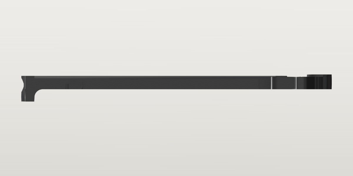
The shaft: its shoulder (where the Army's drawing has the T's front face) to the front hook's tip5.895 in ± 0.01 in 149.7 mmConfirmedWorked out: {aero-charging-handle.length}
Worked out 5.895 in ± 0.01 in used
{aero-charging-handle.length}, harvested
US Army TDP drawing 8448518 (Handle, Charging), rev G, side view: 5.600 and .295.
The standard's, by expression: BCM states no length. "Compatible with Mil-Spec AR-15 Direct Impingement Weapon Systems." (BCM's page): the hook that pulls the carrier is where the standard's is. The handle is placed by it: its tip this far ahead of the receiver's rear face.
The shaft's width0.4 in ± 0.005 in 10.2 mmConfirmedWorked out: {aero-charging-handle.shaft_width}
Worked out 0.4 in ± 0.005 in used
{aero-charging-handle.shaft_width}, harvested
US Army TDP drawing 8448518, plan view: .400 -B-.
The standard's, by expression: the channel it runs in is the standard's. It is the plan photos' scale.
The shaft's thickness0.298 in ± 0.0035 in 7.6 mmConfirmedWorked out: {aero-charging-handle.shaft_thickness}
Worked out 0.2985 in ± 0.0035 in used
{aero-charging-handle.shaft_thickness}, harvested
US Army TDP drawing 8448518, side view: .2985 ±.0035.
The standard's, by expression.
How far a latch stands out past the handle's main body (BCM's figure: taken as from the shaft's side face to the latch's tip, across)1.1 in ± 0.05 in 27.9 mmConfirmedPublished: BCM, BCM® Ambidextrous MK2 Charging Handle - Large Latch (5.56mm/.223) (BCM-GFH-MK2-LRG-AMBI), About this BCM® MK2 Ambi AR-15 Charging Handle, the maker, read Oct 5, 2026
Published “Large latch extends past the main body approximately 1.10".” used
BCM, BCM® Ambidextrous MK2 Charging Handle - Large Latch (5.56mm/.223) (BCM-GFH-MK2-LRG-AMBI), About this BCM® MK2 Ambi AR-15 Charging Handle, the maker, read Oct 5, 2026 the page, harvested Oct 5, 2026
"approximately" is BCM's word: the ± is taken as half its second digit, not its third.
Photo 1.11 in ± 0.02 in
BCM's gallery: the large two-latch handle from above, on white, 1280 x 854, harvested
Scale: the shaft's width column by column (shaft_width). Read by half of what the traced plan is across its two latches' tips (2.623) over the shaft's width: 1.111. By the plain ratio at the T (458 px across the latches, the shaft 70.1 px beside them): 1.106
What the reading of BCM's figure rests on: its medium handle's photo, taken the same way (9b26e2f1d7fd: 397 px across, the shaft 70.1 px), gives 0.93 where BCM says "approximately 0.92".
The maker's figure; its photo agrees within 1% when the figure is read as from the shaft's side face to the latch's tip, and the medium handle's figure and photo agree the same way.
BCM doesn't say where on the main body it is measured from, nor that it is each side's on this two-latch handle.
The key's channel under the shaft: its width0.312 in ± 0.005 in 7.9 mmConfirmedStandard: US Army TDP drawing 8448518 (Handle, Charging), rev G, scale 2/1, PDF page 128, Section A-A
Standard “.312” used
US Army TDP drawing 8448518 (Handle, Charging), rev G, scale 2/1, PDF page 128, Section A-A
With FULL R: its roof is a half round of this width.
The key's channel: its depth from the shaft's underside to the top of its round roof0.25 in ± 0.005 in 6.3 mmConfirmedStandard: US Army TDP drawing 8448518 (Handle, Charging), rev G, scale 2/1, PDF page 128, Section A-A
Standard “.250” used
US Army TDP drawing 8448518 (Handle, Charging), rev G, scale 2/1, PDF page 128, Section A-A
Read as from the open face to the roof's top: the shaft is .2985 thick, which leaves .0485 above it, where the side view's hidden line is.
The front hook: its rear face to its tip0.295 in ± 0.005 in 7.5 mmConfirmedStandard: US Army TDP drawing 8448518 (Handle, Charging), rev G, scale 2/1, PDF page 128, side view
Standard “.295” used
US Army TDP drawing 8448518 (Handle, Charging), rev G, scale 2/1, PDF page 128, side view
The front hook: how far it hangs below the shaft's underside0.275 in ± 0.005 in 7 mmConfirmedStandard: US Army TDP drawing 8448518 (Handle, Charging), rev G, scale 2/1, PDF page 128, side view
Standard “.275 -C-” used
US Army TDP drawing 8448518 (Handle, Charging), rev G, scale 2/1, PDF page 128, side view
Read as from the shaft's underside to the hook's foot (88 px at 316 px/in: .278); from the shaft's top it would end above the underside.
The front hook: the round between its rear face and the shaft's underside0.187 in ± 0.005 in 4.7 mmConfirmedStandard: US Army TDP drawing 8448518 (Handle, Charging), rev G, scale 2/1, PDF page 128, side view
Standard “.187 R” used
US Army TDP drawing 8448518 (Handle, Charging), rev G, scale 2/1, PDF page 128, side view
Across the two guide lugs near the shaft's front end0.488 in ± 0.005 in 12.4 mmConfirmedStandard: US Army TDP drawing 8448518 (Handle, Charging), rev G, scale 2/1, PDF page 128, end view
Standard “.488” used
US Army TDP drawing 8448518 (Handle, Charging), rev G, scale 2/1, PDF page 128, end view
The guide lugs' height, from the shaft's underside up0.119 in ± 0.002 in 3 mmConfirmedStandard: US Army TDP drawing 8448518 (Handle, Charging), rev G, scale 2/1, PDF page 128, end view
Standard “.119 ±.002” used
US Army TDP drawing 8448518 (Handle, Charging), rev G, scale 2/1, PDF page 128, end view
Read as the lugs' height: in the side view they stand on the underside, 36 px high at 316 px/in (.114).
The flat along the shaft's top, between its two chamfers0.14 in ± 0.005 in 3.6 mmProvisionalPhoto: Primary Arms: the part from ahead of its right side and above, 2200 x 1467
Photo 0.14 in ± 0.005 in used
Primary Arms: the part from ahead of its right side and above, 2200 x 1467, harvested
Scale: the shaft's own section in the fitted camera (shaft_width, shaft_thickness). Read by fitted with the camera: the flat's two edges where the shaft's brightness steps, at 0.117 and 0.366 of its width in the photo, station by station; 0.1405. BCM's top photo (02410675303b) has the three bands 23, 25 and 22 px of the shaft's 71: 0.14
The Army's drawing has .15 (8448518, Section A-A).
The shaft's top chamfers: how far below the top their lower edges are0.076 in ± 0.004 in 1.9 mmProvisionalPhoto: Primary Arms: the part from ahead of its right side and above, 2200 x 1467
Photo 0.076 in ± 0.004 in used
Primary Arms: the part from ahead of its right side and above, 2200 x 1467, harvested
Scale: the shaft's own section in the fitted camera (shaft_width, shaft_thickness). Read by fitted with the camera: the near chamfer's lower edge at 0.697 of the shaft's width in the photo, the far one's the far silhouette; 0.0758
The Army's drawing has 30 degrees over .125: .072.
The T, side to side: across the two latches' tips2.623 in ± 0.04 in 66.6 mmProvisionalPhoto: BCM's gallery: the large two-latch handle from above, on white, 1280 x 854
Photo 2.623 in ± 0.04 in used
BCM's gallery: the large two-latch handle from above, on white, 1280 x 854, harvested
Scale: scale from bcm-mk2-charging-handle.shaft_width = 0.4 in, the tube's own width column by column: 71.5 px over columns 50–195, 70.8 px over columns 284–324, 70.3 px over columns 874–894, 70.1 px over columns 988–1000; a line through them (rms 0.14 px) changes -2.0% from column 50 to 1000, so the photo is yawed and one scale would not do. Heights by each column's width; lengths by (u − 640)/width, the lens's axis taken to meet the image at column 640; 176.5 px/in there. The axis is the tube's centre line (tilt -0.17°, rms 0.04 px). Read by height of the traced outline (tools/trace.py); across the two latches' tips (their top faces' edges)
Worked out 2.6 in ± 0.1 in
{.shaft_width} + 2 * {.latch_reach}, harvested
BCM's "approximately 1.10" for a latch, taken from the shaft's side face, each side of the standard's shaft.
BCM's own photo at the scale its shaft's width gives; BCM's figure, read as from the shaft's side, makes 2.60: within 1%, which is what the reading of that figure rests on (latch_reach).
BCM's figure for a latch, taken from the shaft's side, makes it shaft_width + 2 x latch_reach = 2.60.
The T, front to back: its rear grip's rear edge behind the shoulder1.014 in ± 0.02 in 25.8 mmProvisionalPhoto: BCM's gallery: the large two-latch handle from above, on white, 1280 x 854
Photo 1.014 in ± 0.02 in used
BCM's gallery: the large two-latch handle from above, on white, 1280 x 854, harvested
Scale: scale from bcm-mk2-charging-handle.shaft_width = 0.4 in, the tube's own width column by column: 71.5 px over columns 50–195, 70.8 px over columns 284–324, 70.3 px over columns 874–894, 70.1 px over columns 988–1000; a line through them (rms 0.14 px) changes -2.0% from column 50 to 1000, so the photo is yawed and one scale would not do. Heights by each column's width; lengths by (u − 640)/width, the lens's axis taken to meet the image at column 640; 176.5 px/in there. The axis is the tube's centre line (tilt -0.17°, rms 0.04 px). Read by −x_min of the traced outline (tools/trace.py); the rear grip's rear edge behind the shoulder
A latch's thickness: its top face (at its hub, where the pin is) above its underside0.278 in ± 0.015 in 7.1 mmProvisionalPhoto: Primary Arms: the part from ahead of its right side and above, 2200 x 1467
Photo 0.278 in ± 0.015 in used
Primary Arms: the part from ahead of its right side and above, 2200 x 1467, harvested
Scale: the fitted camera; the pins' places from BCM's top photo (02410675303b). Read by the two pins' heights, 0.135 and 0.123 above the channel's axis (0.7 px each off their plan places), over the shaft's underside; the left latch's rear top edge on the skyline reads 0.116
The latches' feet read 0.14 below the channel's axis, the shaft's underside 0.149: taken as flush with it, as the standard's T is.
A latch's ribbed front face: its height0.23 in ± 0.02 in 5.8 mmProvisionalPhoto: Primary Arms: the part from ahead of its right side and above, 2200 x 1467
Photo 0.23 in ± 0.02 in used
Primary Arms: the part from ahead of its right side and above, 2200 x 1467, harvested
Scale: the fitted camera; the latch's front edge in plan from BCM's top photo (02410675303b). Read by nine grooves on the right latch's front face, each one's two ends put on the plan's front edge: 0.214 to 0.254 high, their feet 0.128 to 0.150 below the channel's axis, their tops 0.065 to 0.110 above it (the top face's front edge is rounded off)
The T's height: the rear grip's top above the shaft's underside0.33 in ± 0.03 in 8.4 mmProvisionalPhoto: Primary Arms: the part from ahead of its right side and above, 2200 x 1467
Photo 0.33 in ± 0.03 in used
Primary Arms: the part from ahead of its right side and above, 2200 x 1467, harvested
Scale: the fitted camera; the T's rear outline and the rear grip's lobes in plan from BCM's top photo (02410675303b). Read by the first dark pixel down each of twelve columns over the rear grip, put on the plan's rear outline: 0.160 to 0.205 above the channel's axis (0.18 at the middle), a lower bound for anything ahead of that edge; and the lobes' plan drawn over the photo at 0.16, 0.20, 0.24 and 0.28: the far lobe's top lies on 0.16 to 0.17, the near one's on 0.18 to 0.20, and at 0.24 both stand clear above the photo's. Taken as 0.18 above the axis, over the shaft's underside
The rear grip's lobes and the rim between them read alike within 0.03. A first reading of 0.49 (a lobe's dark front face taken as upright on the plan's line) was wrong: drawn over the photo at that height the lobes stand clear above it.
The grooves on a latch's front face: their pitch0.06 in ± 0.003 in 1.5 mmProvisionalPhoto: Primary Arms: the part from ahead of its right side and above, 2200 x 1467
Photo 0.06 in ± 0.003 in used
Primary Arms: the part from ahead of its right side and above, 2200 x 1467, harvested
Scale: the fitted camera; the latch's front edge in plan from BCM's top photo (02410675303b). Read by nine grooves on the right latch from 0.628 to 1.109 off the centre line: 0.060 apart. The plan's outline has the same teeth along that edge, 0.058 to 0.063 apart
The grooves on a latch's front face: how many10ProvisionalPhoto: BCM's gallery: the large two-latch handle from above, on white, 1280 x 854
Photo 10 count used
BCM's gallery: the large two-latch handle from above, on white, 1280 x 854, harvested
Scale: none: a count. Read by the teeth along the right latch's front edge in the traced outline, 0.58 to 1.08 off the centre line; Primary Arms' oblique photo (68a6620f0132) shows nine of them
Counted where the two photos show them; more may lie under the rear grip's lobe.
The grooves on a latch's front face: their depth0.02 in ± 0.01 in 0.5 mmProvisionalPhoto: BCM's gallery: the large two-latch handle from above, on white, 1280 x 854
Photo 0.02 in ± 0.01 in used
BCM's gallery: the large two-latch handle from above, on white, 1280 x 854, harvested
Scale: the shaft's width column by column (shaft_width). Read by how far the traced outline's teeth step in and out along the right latch's front edge: 0.018 to 0.023
The grooves on a latch's front face: the first one's distance off the shaft's centre line0.58 in ± 0.01 in 14.7 mmProvisionalPhoto: BCM's gallery: the large two-latch handle from above, on white, 1280 x 854
Photo 0.58 in ± 0.01 in used
BCM's gallery: the large two-latch handle from above, on white, 1280 x 854, harvested
Scale: the shaft's width column by column (shaft_width). Read by the first tooth of the traced outline along the right latch's front edge, 0.576 to 0.588 off the centre line
The shaft's top chamfers: where they have run out, ahead of the shoulder0.235 in ± 0.015 in 6 mmConfirmedStandard: US Army TDP drawing 8448518 (Handle, Charging), rev G, scale 2/1, PDF page 128, plan view
Standard “.235 ±.015” used
US Army TDP drawing 8448518 (Handle, Charging), rev G, scale 2/1, PDF page 128, plan view
With ".25 R TRUE 2 PLACES": from the T's front face to where the chamfers' round run-out ends. BCM's top photo has its flat widen to the shaft's full width 0.23 ahead of the shoulder.
The latches' two pins: how far behind the shoulder0.368 in ± 0.01 in 9.3 mmProvisionalPhoto: BCM's gallery: the large two-latch handle from above, on white, 1280 x 854
Photo 0.368 in ± 0.01 in used
BCM's gallery: the large two-latch handle from above, on white, 1280 x 854, harvested
Scale: the shaft's width column by column (shaft_width). Read by the two bright pin ends' centres, at pixels (1144.3, 381.0) and (1144.0, 470.7), through the plan's own map: 0.369 and 0.367 behind the shoulder's column
The latches' two pins: how far each is off the shaft's centre line0.257 in ± 0.006 in 6.5 mmProvisionalPhoto: BCM's gallery: the large two-latch handle from above, on white, 1280 x 854
Photo 0.257 in ± 0.006 in used
BCM's gallery: the large two-latch handle from above, on white, 1280 x 854, harvested
Scale: the shaft's width column by column (shaft_width). Read by the two bright pin ends' centres through the plan's own map: 0.256 to the right and 0.258 to the left
The latches' pins: their ends' diameter0.092 in ± 0.01 in 2.3 mmProvisionalPhoto: BCM's gallery: the large two-latch handle from above, on white, 1280 x 854
Photo 0.092 in ± 0.01 in used
BCM's gallery: the large two-latch handle from above, on white, 1280 x 854, harvested
Scale: the shaft's width column by column (shaft_width): 174.6 px/in at the pins. Read by each bright pin end is 16 px across (15 to 16 down); the glare may widen it
Roll pins: Primary Arms' photos show their ends as rings.
The latches' hubs: the radius of their outlines about the pins0.25 in ± 0.01 in 6.3 mmProvisionalPhoto: BCM's gallery: the large two-latch handle from above, on white, 1280 x 854
Photo 0.25 in ± 0.01 in used
BCM's gallery: the large two-latch handle from above, on white, 1280 x 854, harvested
Scale: the shaft's width column by column (shaft_width): 174.6 px/in at the pins. Read by the right hub's round outline spans rows 337 to 425 and columns 1100 to 1188 (88 px across); the two hubs' outlines meet on the shaft's centre line, where the pins' distance off it (pin_off_centre) would have them
What it goes with
By the way it mounts, and the figures each part on file states: a part whose figures say it doesn't fit is left out, and one whose fit can't be checked from what is published is marked. A check is against published figures, not a guarantee.
Charging handle channel
- Uppers
- Aero Precision M4E1 Enhanced Upper Receiver Stripped, Aero Precision M4E1 Threaded upper receiver, BCM M4 Upper Receiver Assembly (w/ Laser T-Markings), Expo Arms 7075 Stripped AR-15 Upper Receiver, Geissele Automatics Super Duty Stripped Upper Receiver, Palmetto State Armory AR-15 Stripped Upper Receiver
Prices on file
Each seller's latest reading of its own page: before tax and shipping, and not a quote. The pages are read again every night.
- BCM $89.95 Nov 21, 2026, in stock that day
- Primary Arms $89.95 Nov 21, 2026, in stock that day
- Alexander's Store $89.95 Nov 18, 2026, in stock that day
- Scheels $89.99 Oct 5, 2026, in stock that day
- Faxon Firearms $91.95 Nov 21, 2026, out of stock that day