Hand stop
Magpul M-LOK Index Panel
The index panel of Magpul's M-LOK Hand Stop Kit (MAG608), sold only in that kit: a low fin that gives the support hand a reference point, on a plate one M-LOK slot long. Magpul: "one M-LOK Index panel, which is reversible for a custom fit". Black, FDE, ODG, Stealth Gray.
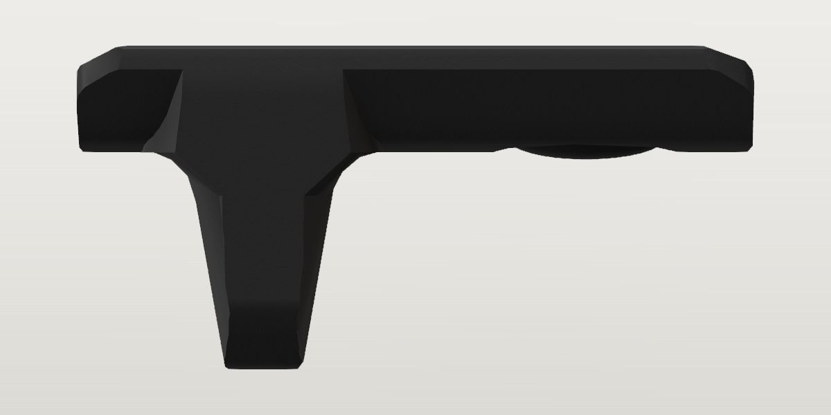
- Weight
- 0.3 oz ± 0.05 oz Provisionalpublished: Wing Tactical, Magpul M-LOK Handstop Kit (MAG-608), Specifications (source of the figures unstated), a seller, read Oct 5, 2026
- Lowest price
- Sold in the Magpul M-LOK Hand Stop Kit, not by itself
- Colours
- Black, FDE, ODG, Stealth Gray
- Drawn as
- modelled
- Maker's page
- magpul.com
In “Two-tone 16 in, Stealth Gray and soft-shooting”, a build on the start page, in place of its Magpul M-LOK Hand Stop.
Its figures
Every figure the site draws and checks it by, with where it came from. Open one for each source's reading, and why one is used where they differ.
Overall length (the plate, along the handguard)1.558 in ± 0.015 in 39.6 mmCorroboratedPhoto: Supplied in chat 2026-10-02: a gallery image of an M-LOK handguard, straight side view, the hand stop and the index panel installed, rail teeth along the top, 2796 x 1290
Photo 1.558 in ± 0.015 in used
Supplied in chat 2026-10-02: a gallery image of an M-LOK handguard, straight side view, the hand stop and the index panel installed, rail teeth along the top, 2796 x 1290, from the site owner
Scale: the handguard's rail teeth in the same image (calibrate.py rail: 16 slots, 132.58 px/slot, drift +0.04%, rms 0.002 in): 336.5 px/in. Checked in the plate's own plane: the seams between the pieces on the bottom face (u 1219, 1754, 2283) are 532 px apart, 40.2 mm on that scale for the 40 mm slot pitch (std.mlok.slot_pitch). Read by the plate's two ends, each between the seam's darkest column (u 1754 and 2283, rows 725 to 770: 529 px) and where the tone is halfway back to the plate's own (u 1758.4 and 2278.2: 519.8 px): 524.4 px ± 4.6. Its rounded ends are in the seams' shadow
Photo 1.559 in ± 0.015 in
US D755,334 S, Magpul, FIG. 7 top plan: the mounting face, in broken lines; the patent office's copy, page 8, 300 dpi, harvested
Scale: the screw hole's centre (fitted circle, row 1178.6, rms 0.6 px) and the middle of the second pair of bosses (rows 1907 to 2516: 2211.2), 1032.6 px apart, taken as the M-LOK interval (std.mlok.interval, 20 mm: Magpul's FAQ), as the hand stop's two screws are. Read by the plan view's length, 2044 px (rows 673 to 2717), over that spacing; ± 8 px on the two centres
Measured on an image of the product, in the plane of its scale. The patent's top plan, scaled by its own bosses as one M-LOK interval, agrees within 0.001 in. Both are a little under 40 mm, the slot pitch the pieces stand at.
The plate covers one M-LOK slot pitch less the seams to its neighbours (39.6 mm read). The hand stop's plate reads 1.575 ± 0.012 in the same image, by one end and a seam's middle; the two are the same within their ±. A retailer's staff put each of the kit's panels at "approximately 40 mm" (OpticsPlanet's Q&A, quoted in the hand stop's seed; not harvested for this part).
Height (how far it stands off the handguard's face)0.745 in ± 0.03 in 18.9 mmCorroboratedPhoto: US D755,334 S (Magpul, 'Index attachment for a firearm'), FIG. 5 left side elevation, 300 dpi
Photo 0.745 in ± 0.03 in used
US D755,334 S (Magpul, 'Index attachment for a firearm'), FIG. 5 left side elevation, 300 dpi, harvested
Scale: scale from magpul-mlok-index-panel.length = 1.558 in (x-extent 2159 px → 1385.8 px/in). Read by height of the traced outline (tools/trace.py); the patent's side elevation scaled to the plate's length: the ears' tips (the outermost line on the mounting side, in broken strokes; the shading's ticks outside it left out) to the fin's tip. The front elevation, scaled by this and by the plan's width, fits both with one scale within 0.1%
Photo 0.704 in ± 0.012 in
Supplied in chat 2026-10-02: a gallery image of an M-LOK handguard, straight side view, the hand stop and the index panel installed, rail teeth along the top, 2796 x 1290, from the site owner
Scale: the handguard's rail teeth in the same image: 336.5 px/in. Read by the plate's top edge where it shows (the dark line under the handguard's band, rows 710 to 715, down which the pieces' seams begin: row 714 ± 2) to the fin's lowest point (row 950.8): 236.8 px. The band above that line (rows 687 to 712, 0.075 in) runs unbroken across the seams and has dark openings in it: it is the handguard's lower face, not the plate
Line art, whole and orthographic. In the image the plate's top is dark against the handguard, and what shows of it is 0.04 in less than the drawing's: all of the difference is in the plate (0.213 in showing against the drawing's 0.246; the fin below it agrees within 0.008, fin_height). Either the ears' last 0.03 in is hidden there or the drawing's broken outermost line stands that far off the part; the bearing band is placed from the drawing.
From the ears' tips (the outermost line on the mounting side) to the fin's tip. The band between the ears, which bears on a handguard, is mounting_band_depth nearer the tip.
Width (side to side)1.038 in ± 0.03 in 26.4 mmProvisionalPhoto: US D755,334 S, Magpul, FIG. 8 bottom plan; the patent office's copy, page 9, 300 dpi
Photo 1.038 in ± 0.03 in used
US D755,334 S, Magpul, FIG. 8 bottom plan; the patent office's copy, page 9, 300 dpi, harvested
Scale: the plan view's own length, 1866 px (rows 786 to 2652), as the plate's length (.length, 1.558 in). Read by the plan view's width, 1243 px (columns 638 to 1881), at the ears' tips (the widest: the plate's outer face is narrower). FIG. 7 reads the same ratio (1362 over 2044: 0.666). ± covers the length's ± and a design patent's fidelity
No published figure. From Magpul's design patent, scaled by the plate's length. The hand stop's, from its own patent the same way, is 1.053 (its plate read 1% longer): Magpul's photos show the kit's pieces in a row with their sides in line.
M-LOK slots its lugs span1CorroboratedPhoto: US D755,334 S, Magpul, FIG. 7 top plan: the mounting face, in broken lines; the patent office's copy, page 8, 300 dpi
Photo 1 count used
US D755,334 S, Magpul, FIG. 7 top plan: the mounting face, in broken lines; the patent office's copy, page 8, 300 dpi, harvested
Scale: the plan view's length as the plate's (.length). Read by one screw hole 0.385 in from the plate's rear end and a pair of bosses 0.787 in ahead of it, on a plate 1.558 in long: one 32 mm slot takes both, and the plate covers that slot's pitch
Published “The hand stop occupies two M-LOK slots, the index panel one slot, and the rail cover spans two.”
rifleconfigurator.com, Magpul M-LOK Hand Stop Kit (a configurator site; source of the statement unstated), a review, read Oct 5, 2026 the page, harvested Oct 5, 2026
Read on Magpul's own drawing of the mounting face; the site's unattributed sentence says the same of this piece.
One screw and one T-nut (FIG. 7 draws one hole; Wing Tactical's photo of its mounting side shows one, and its photo of the kit's hardware three T-nuts: two for the hand stop). A second pair of bosses with no screw stands either side of the fin's hollow, one M-LOK interval from the screw: the two pairs go one in each half of a slot, and the plate covers that slot's pitch. Magpul's sheet names no count.
Reach inside the handguard (below the mounting face, tightened)No value yetMissingNo source yet
Not sourced (as for the hand stop and the MVG: Magpul publishes no T-nut figure). FIG. 3 draws the lug that stands in the slot 0.06 in above the band, in broken lines; the T-nut beyond it isn't drawn.
Rear lug's centre ahead of the part's rear end (its screw and T-nut)0.387 in ± 0.012 in 9.8 mmConflictPhoto: US D755,334 S, Magpul, FIG. 8 bottom plan; the patent office's copy, page 9, 300 dpi
Photo 0.387 in ± 0.012 in used
US D755,334 S, Magpul, FIG. 8 bottom plan; the patent office's copy, page 9, 300 dpi, harvested
Scale: the plan view's own length, 1866 px, as the plate's length (.length, 1.558 in). Read by the screw hole's four circles, drawn in broken lines, fitted on one centre (row 2189.1, rms 0.6 to 0.7 px): 462.9 px from the plate's screw end (row 2652)
Photo 0.385 in ± 0.012 in
US D755,334 S, Magpul, FIG. 7 top plan: the mounting face, in broken lines; the patent office's copy, page 8, 300 dpi, harvested
Scale: the plan view's own length, 2044 px, as the plate's length (.length, 1.558 in). Read by the screw hole's circle fitted (row 1178.6, rms 0.6 px): 505.6 px from the plate's screw end (row 673)
Photo 0.463 in ± 0.02 in
Supplied in chat 2026-10-02: a gallery image of an M-LOK handguard, straight side view, the hand stop and the index panel installed, rail teeth along the top, 2796 x 1290, from the site owner
Scale: the handguard's rail teeth in the same image: 336.5 px/in. Read by the middle of the screw's head where it stands below the plate (u 2088.7 to 2160.9 at rows 790 to 793: 2124.8) from the plate's end on that side (u 2278.2 to 2283: 2280.6): 155.8 px; ± covers the end's 4.6 px and the head's 3
Magpul's drawing, on which both plan views agree within 0.002 in, and which puts the screw half an M-LOK interval (10 mm) from the plate's middle, where a T-nut in a slot under the plate's middle goes. The image has the screw 0.08 in nearer the fin (8 mm from the plate's middle) and the fin as much nearer its end (fin_x), while the distance between the two agrees with the patent within 2%: its seams are what part from the drawing, and it is a rendering whose source page isn't on file.
patent-bottom and render differ by 0.076 in beyond what each states it is good to.
patent-top and render differ by 0.078 in beyond what each states it is good to.
The part's rear end is the plate's end away from the fin, as Magpul's pictures of the kit have it (the fin at the front of its plate, ahead of the hand stop). The second pair of bosses, either side of the fin's hollow, is 0.386 in from the front end and 0.787 in (20.0 mm) ahead of the screw: the middle of the two pairs is the plate's middle within 0.001 in.
The fin's middle ahead of the part's rear end1.127 in ± 0.012 in 28.6 mmConflictPhoto: US D755,334 S, Magpul, FIG. 5 left side elevation; the patent office's copy, page 6, 300 dpi
Photo 1.127 in ± 0.012 in used
US D755,334 S, Magpul, FIG. 5 left side elevation; the patent office's copy, page 6, 300 dpi, harvested
Scale: the side elevation's own length, 2163 px (rows 649 to 2811), as the plate's length (.length, 1.558 in). Read by the middle of the fin's tip (rows 2099 to 2328: 2213.5) from the plate's far end (row 649): 1564.5 px. FIG. 8 has it at 0.7245 of the length (the fin's lines are symmetric about row 1300) and FIG. 7's hollow at 0.7248: 1.129 in both
Photo 1.19 in ± 0.016 in
Supplied in chat 2026-10-02: a gallery image of an M-LOK handguard, straight side view, the hand stop and the index panel installed, rail teeth along the top, 2796 x 1290, from the site owner
Scale: the handguard's rail teeth in the same image: 336.5 px/in. Read by the middle of the fin's two flanks (u 1880.0 at rows 860, 900 and 945, within 0.3 px) from the plate's far end (u 2278.2 to 2283: 2280.6): 400.6 px (with the screw's head, 244.8 px from the fin's middle: 0.728 in, where the patent has 0.740)
Three views of Magpul's drawing agree within 0.002 in. The image has the fin 0.06 in nearer its end of the plate, and the screw with it (lug_x): see there.
patent-side and render differ by 0.063 in beyond what each states it is good to.
The fin below the plate's outer face0.498 in ± 0.012 in 12.6 mmCorroboratedPhoto: US D755,334 S, Magpul, FIG. 5 left side elevation; the patent office's copy, page 6, 300 dpi
Photo 0.498 in ± 0.012 in used
US D755,334 S, Magpul, FIG. 5 left side elevation; the patent office's copy, page 6, 300 dpi, harvested
Scale: the side elevation's own length, 2163 px, as the plate's length (.length, 1.558 in). Read by the plate's outer face (the heavy line at columns 1194 to 1199) to the fin's tip (the heavy line at columns 1886 to 1891): 692 px
Photo 0.49 in ± 0.008 in
Supplied in chat 2026-10-02: a gallery image of an M-LOK handguard, straight side view, the hand stop and the index panel installed, rail teeth along the top, 2796 x 1290, from the site owner
Scale: the handguard's rail teeth in the same image: 336.5 px/in. Read by the plate's outer face on its smooth stretch (row 785.8 at half tone, u 1975 to 2030) to the fin's lowest point (row 950.8, u 1862 to 1900): 165.0 px. The fin's flanks lean 11.5 degrees each (98.6 px wide at row 860, 82.3 at row 900), the patent's 10.5 to 11
The outline's own; the image agrees within 1.6%, which with the plate's length is the two sizes that agree at one scale.
The one height both sources show against white: the plate's own top is dark against the handguard in the image.
Screw hole (through the plate)0.219 in ± 0.008 in 5.6 mmProvisionalPhoto: US D755,334 S, Magpul, FIG. 8 bottom plan; the patent office's copy, page 9, 300 dpi
Photo 0.219 in ± 0.008 in used
US D755,334 S, Magpul, FIG. 8 bottom plan; the patent office's copy, page 9, 300 dpi, harvested
Scale: the plan view's own length, 1866 px, as the plate's length (.length, 1.558 in). Read by the innermost of the four broken-line circles, fitted: radius 130.9 px (rms 0.6). FIG. 7 draws the same hole from the mounting side: radius 143.6 px on a 2044 px plate, 0.219 in
Screw's recess in the outer face, at its rim0.429 in ± 0.01 in 10.9 mmProvisionalPhoto: US D755,334 S, Magpul, FIG. 8 bottom plan; the patent office's copy, page 9, 300 dpi
Photo 0.429 in ± 0.01 in used
US D755,334 S, Magpul, FIG. 8 bottom plan; the patent office's copy, page 9, 300 dpi, harvested
Scale: the plan view's own length, 1866 px, as the plate's length (.length, 1.558 in). Read by the outermost of the four broken-line circles, fitted: radius 256.9 px (rms 0.7), on the hole's centre
FIG. 8 draws three circles round the hole in broken lines: this one, one of 0.400 in (radius 239.3 px) and screw_recess_floor_diameter. FIG. 2 shows them as a dish with the hole in its floor. How deep it is no view gives.
Screw's recess in the outer face, the innermost of its three circles0.36 in ± 0.01 in 9.1 mmProvisionalPhoto: US D755,334 S, Magpul, FIG. 8 bottom plan; the patent office's copy, page 9, 300 dpi
Photo 0.36 in ± 0.01 in used
US D755,334 S, Magpul, FIG. 8 bottom plan; the patent office's copy, page 9, 300 dpi, harvested
Scale: the plan view's own length, 1866 px, as the plate's length (.length, 1.558 in). Read by the third circle in from the rim, fitted: radius 215.4 px (rms 0.6), on the hole's centre
Mounting face: the band between the ears, below the ears' tips0.111 in ± 0.01 in 2.8 mmProvisionalPhoto: US D755,334 S (Magpul, 'Index attachment for a firearm'), FIG. 3 front elevation, 300 dpi
Photo 0.111 in ± 0.01 in used
US D755,334 S (Magpul, 'Index attachment for a firearm'), FIG. 3 front elevation, 300 dpi, harvested
Scale: the traced front elevation's own scale (profiles.front: magpul-mlok-index-panel.height and .width, 1355.6 px/in). Read by the flat between the ears on the traced outline, at y 0.110 to 0.112 from z -0.345 to +0.339, against the ears' tips at y 0 (z ±0.50)
The band is what bears on a handguard's M-LOK face, as the hand stop's does (the same plate: its band is 0.116 in below its ears' tips and 0.698 across): the ears slope out and up from its edges and run down either side of a face narrower than the band. The drawing has it in broken lines (rows 735 to 737 and 749 of FIG. 3), with the lug that stands in the slot a broken box 0.06 in high and 0.27 in wide above it (a 7 mm slot's, std.mlok.slot_width); a third line 0.05 in further in, in solid dots, is the plate's end face. Wing Tactical's photo of the mounting side shows the flat band, the ears and the bosses.
Mounting face: the band between the ears, across0.684 in ± 0.02 in 17.4 mmProvisionalPhoto: US D755,334 S (Magpul, 'Index attachment for a firearm'), FIG. 3 front elevation, 300 dpi
Photo 0.684 in ± 0.02 in used
US D755,334 S (Magpul, 'Index attachment for a firearm'), FIG. 3 front elevation, 300 dpi, harvested
Scale: the traced front elevation's own scale (profiles.front, 1355.6 px/in). Read by the flat between the ears on the traced outline: z -0.345 to +0.339
Screw's head, across0.364 in ± 0.025 in 9.2 mmProvisionalPhoto: Magpul's gallery for MAG608, mag608_fde_2.png, 1200 x 1200: the FDE kit's pieces put together with their screws in, three-quarter from the outer side; filed with the hand stop
Photo 0.364 in ± 0.025 in used
Magpul's gallery for MAG608, mag608_fde_2.png, 1200 x 1200: the FDE kit's pieces put together with their screws in, three-quarter from the outer side; filed with the hand stop, harvested
Scale: the recess's rim in the same view, as .screw_recess_diameter (0.429 in): both are circles on one axis a few hundredths of an inch apart in depth, so their long axes are in the ratio of their diameters. Read by the dark head's long axis 58.5 px (columns 323 to 383 at luminance under 75) against the rim's 69 px, read on a tenfold enlargement; ± covers a pixel and a half on each and the rim's soft edge
Magpul publishes no figure for the kit's screws. A wide low head with a six-lobe socket (Wing Tactical's photo of the kit's hardware: six alike). It is the recess's innermost circle (screw_recess_floor_diameter, 0.360 in) within the reading: the head fills the dish's floor.
Screw's head: its crown above the plate's outer face0.034 in ± 0.008 in 0.9 mmProvisionalPhoto: Supplied in chat 2026-10-02: a gallery image of an M-LOK handguard, straight side view, the hand stop and the index panel installed, rail teeth along the top, 2796 x 1290
Photo 0.034 in ± 0.008 in used
Supplied in chat 2026-10-02: a gallery image of an M-LOK handguard, straight side view, the hand stop and the index panel installed, rail teeth along the top, 2796 x 1290, from the site owner
Scale: the handguard's rail teeth in the same image: 336.5 px/in. Read by the plate's outer face at half tone on its smooth stretch (rows 785.4 to 786.7, u 1975 to 2025) to the head's lowest point (row 797.1, u 2124 to 2130): 11.5 px; ± covers 2 px and the face's own 1.3 px
A rendering whose source page isn't on file (lug_x's note: its seams part from the drawing; a height across 0.03 in doesn't depend on them).
What it goes with
By the way it mounts, and the figures each part on file states: a part whose figures say it doesn't fit is left out, and one whose fit can't be checked from what is published is marked. A check is against published figures, not a guarantee.
M-LOK
- Uppers
- Nordic Components 22RB .22 LR upper, 16" (fit unchecked), Panzer Arms AR57 ULT Complete AR-15 Upper Receiver - 5.7x28mm - 12" (fit unchecked), Panzer Arms AR57 Ultra Light Tactical Complete AR-15 Upper Receiver - 5.7x28mm - 16" (fit unchecked)
- Handguards
- Aero Precision AR15 10.3" R-ONE M-LOK handguard (fit unchecked), Aero Precision AR15 12.7" R-ONE M-LOK handguard (fit unchecked), Aero Precision AR15 15" Enhanced M-LOK Handguard, Gen 2 (fit unchecked), Aero Precision AR15 15" R-ONE M-LOK handguard (fit unchecked), Aero Precision AR15 15" S-ONE M-LOK Handguard (fit unchecked), Aero Precision AR15 16.6" R-ONE M-LOK handguard (fit unchecked), Aero Precision AR15 7.3" R-ONE M-LOK handguard (fit unchecked), Aero Precision AR15 9.3" R-ONE M-LOK handguard (fit unchecked), BCM MCMR-10 (M-LOK® Compatible* Modular Rail) (fit unchecked), BCM MCMR-13 (M-LOK® Compatible* Modular Rail) (fit unchecked), BCM MCMR-15 (M-LOK® Compatible* Modular Rail) (fit unchecked), BCM PMCR (Polymer M-LOK® Compatible Rail)* Carbine Length-BLACK (fit unchecked), BCM PMCR (Polymer M-LOK® Compatible Rail)* Mid Length-BLACK (fit unchecked), Expo Arms Free Float AR-15 Handguard - M-LOK - 15" (fit unchecked), Geissele Automatics 10.5" Super Modular Rail MK16 M-LOK (fit unchecked), Geissele Automatics 13.5" Super Modular Rail MK16 M-LOK (fit unchecked), Geissele Automatics 15" Super Modular Rail MK16 M-LOK (fit unchecked), Magpul MOE SL® Hand Guard, Carbine-Length – AR15/M4 (fit unchecked), Magpul MOE SL® Hand Guard, Mid-Length – AR15/M4 (fit unchecked), Magpul MOE® M-LOK® Hand Guard, Carbine-Length – AR15/M4 (fit unchecked), Magpul MOE® M-LOK® Hand Guard, Mid-Length – AR15/M4 (fit unchecked), MAS Defense 12.62" NERO M-LOK FREE FLOAT (fit unchecked), MAS Defense 15" NERO M-LOK FREE FLOAT (fit unchecked), MAS Defense 9.87" NERO M-LOK FREE FLOAT (fit unchecked), Midwest Industries AR-15/M16 Two Piece Drop-In Handguard, M-LOK® (Carbine) (fit unchecked), Midwest Industries AR-15/M16 Two Piece Drop-In Handguard, M-LOK® (Mid-Length) (fit unchecked), Midwest Industries Combat Rail One Piece Free Float Handguard, M-LOK™ (15") (fit unchecked)
- Adapter plates
- Magpul M-LOK Hand Stop MOE Adapter (fit unchecked)