Vertical grip
BCM Vertical Grip Mod 3 (M-LOK® Compatible*)
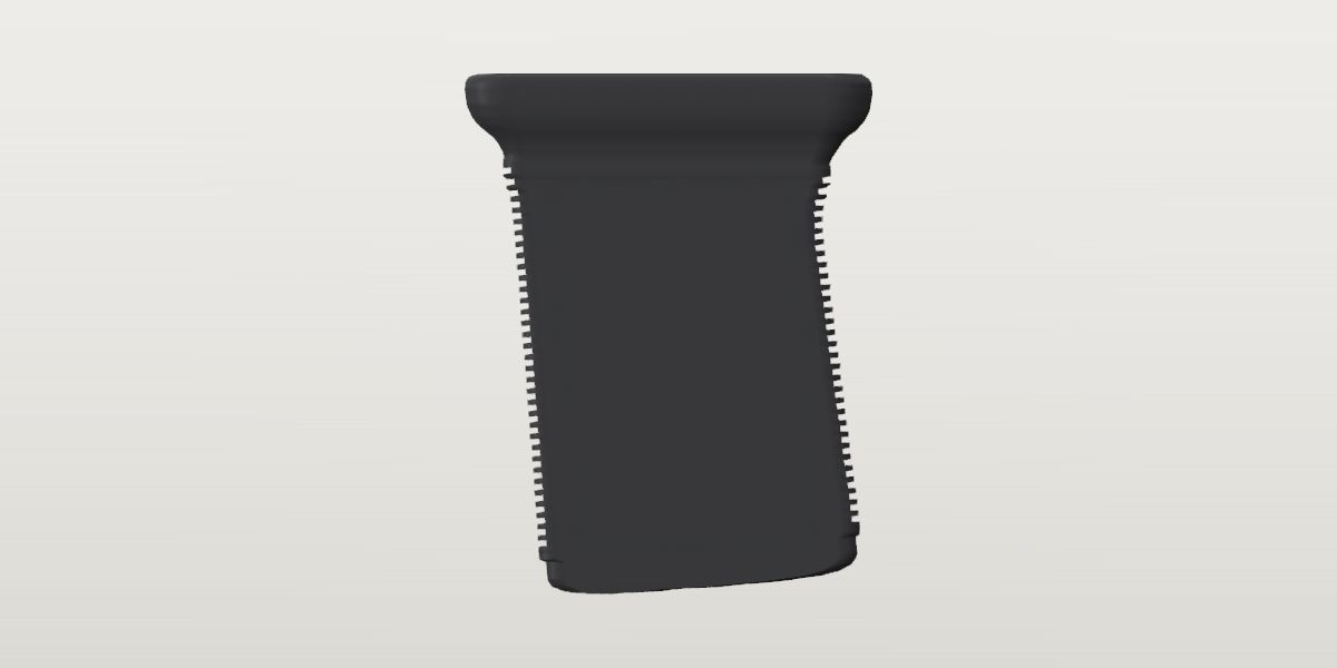
BCM's Vertical Grip Mod 3, the direct-attach M-LOK version: a low-profile polymer vertical grip, 2.2 in long and 2.8 in tall, its body raked 5 degrees to the mounting face, flat textured sides and ridged ends, 1.9 oz. Mounts either way round. Black and Flat Dark Earth.
- Weight
- 1.9 oz ± 0.05 oz Confirmedpublished: BCM, BCM® Vertical Grip Mod 3 (M-LOK® Compatible*) - Black, Description, the maker, read Oct 19, 2026
- Lowest price
- $18.95 at BCM, read Nov 21, 2026 (Black)
- Maker's number
- BCM-VG-MCMR-MOD-3-BLK
- Colours
- Black, Flat Dark Earth
- Drawn as
- modelled
- Maker's page
- bravocompanyusa.com
Added to “22RB .22 LR rifle”, a build on the start page, where the designer starts a new vertical grip.
Its figures
Every figure the site draws and checks it by, with where it came from. Open one for each source's reading, and why one is used where they differ.
Overall length (along the handguard: the plate, end to end)2.166 in ± 0.03 in 55 mmCorroboratedPhoto: Primary Arms BCM-VG-MCMR-MOD-3-BLK_00.jpg and _01.jpg: the grip alone on white, upright, its two sides, straight side views along the handguard, 1152 x 768
Photo 2.166 in ± 0.03 in used
Primary Arms BCM-VG-MCMR-MOD-3-BLK_00.jpg and _01.jpg: the grip alone on white, upright, its two sides, straight side views along the handguard, 1152 x 768, harvested
Scale: the two T-nuts' centres as std.mlok.interval (20 mm): 161.9 px in _00 (the nuts' tops 160.8, their round bosses 163.0) and 160.5 px in _01 (161.0 and 160.0); 205.6 and 203.8 px/in. Read by the silhouette's extent along the mounting face (luminance 200, sub-pixel): 448 px in _00 (2.179 in) and 438.9 px in _01 (2.153 in); the mean, the two photos' difference in the ±
Photo 2.154 in ± 0.07 in
BCM's BCM-VG-MCMR-MOD-3-BLK-6: the grip on a BCM MCMR handguard, from below the rifle's right side, the muzzle to the right, 1500 x 1000, harvested
Scale: std.mlok.slot_pitch (40 mm), read locally: the centroids of the see-through slots in the row beside the grip, along the handguard's axis in the picture (28.8 degrees below the horizontal): 204.5 px a pitch behind the grip and 217.3 a pitch over the two pitches ahead of it, 214.9 px interpolated at the grip's middle. Read by the plate's ends where its outline meets the handguard's lower edge, (400, 425) and (660, 563) px: 294.1 px along the axis, 1.369 pitches. The ± is the photo's: the slots' row lies a little above the plate's ends, the pitch changes 6% across the picture, and a see-through gap's middle moves along the part with the angle the line of sight crosses it at (CLAUDE.md), which the near edges would not
Two straight views, the smaller ±; the installed photo, scaled by the handguard's slots with nothing taken from the grip, agrees within 0.6%.
The plate on the mounting face is the grip's longest part; the body under it is 1.68 in at its crests. The two readings are independent: the installed photo is scaled by the handguard's slots, the side views by the T-nuts' spacing taken as the M-LOK interval, which the first reading confirms (lug_spacing).
Height (how far it stands off the handguard's face: the mounting face to the base's lowest point)2.768 in ± 0.041 in 70.3 mmProvisionalPhoto: Primary Arms BCM-VG-MCMR-MOD-3-BLK_00.jpg: the grip alone on white, upright, its marked side, a straight side view along the handguard, 1152 x 768
Photo 2.768 in ± 0.041 in used
Primary Arms BCM-VG-MCMR-MOD-3-BLK_00.jpg: the grip alone on white, upright, its marked side, a straight side view along the handguard, 1152 x 768, harvested
Scale: scale from bcm-vertical-grip-mod-3-mlok.length = 2.166 in (x-extent 450 px → 207.5 px/in). Read by height of the traced outline (tools/trace.py); the leveled outline's extent from the mounting face to the base's lowest point (its front corner), at the scale the length sets
Filled by the side trace (profiles.side, its targets). The base isn't parallel to the mounting face (base_angle): the grip is 0.1 in taller at one end than the other.
Width (side to side: the plate, its widest)1.02 in ± 0.08 in 25.9 mmProvisionalPhoto: BCM's BCM-VG-MCMR-MOD-3-BLK-3: the grip upright, its marked side to the lens, from about 34 degrees above, the mounting face's rim and its cells in view, 1500 x 1000
Photo 1.02 in ± 0.08 in used
BCM's BCM-VG-MCMR-MOD-3-BLK-3: the grip upright, its marked side to the lens, from about 34 degrees above, the mounting face's rim and its cells in view, 1500 x 1000, harvested
Scale: the plate's length across the picture, 479 px (474 to 953), as bcm-vertical-grip-mod-3-mlok.length. Read by the camera's elevation from the texture panel's foreshortening, a rectangle in the side face: 1.25 tall for its length here against 1.51 in the straight side view, so cos 34.3 degrees; the rim's outline across the mounting face from its far edge to its near edge 120 to 134 px down the picture (where the rim's top ends and the flare begins is a round), over sin 34.3 degrees and at the plate's scale: 0.97 to 1.08 in. The middle, the range and the lens's perspective in the ±
No view on file is square to the grip's end, and no page gives a width: this is read through the foreshortening of BCM's view from above, and is the least certain size on file.
Body width (side to side, between the flat sides under the flare)0.92 in ± 0.1 in 23.4 mmProvisionalPhoto: BCM's BCM-VG-MCMR-MOD-3-FDE-2: the Flat Dark Earth grip from above its front right corner, 1500 x 1000
Photo 0.92 in ± 0.1 in used
BCM's BCM-VG-MCMR-MOD-3-FDE-2: the Flat Dark Earth grip from above its front right corner, 1500 x 1000, harvested
Scale: a ratio: none. Read by a yawed view sees the side face as its length times cos(yaw) (295 px) and an end face as the body's width times sin(yaw) (60 px); the plate's horizontal extent (450 px) is its length times cos(yaw) plus its width times sin(yaw), and its length is 1.30 of the body's crest length (the side view): the yaw drops out and the plate is 1.108 times the body's width. Read square on (no perspective), with the corners' rounds ignored: hence the ±
The plate overhangs the flat sides (the flare runs all round, much less across than along). Derived from the plate's width and the ratio of the two read on one photo.
M-LOK slots its lugs span1ProvisionalWorked out: Two T-nuts lug_spacing apart (19.9 mm, the interval within 0.5%) fit one M-LOK slot (std.mlok.slot_length, 32 mm)
Worked out 1 count used
Two T-nuts lug_spacing apart (19.9 mm, the interval within 0.5%) fit one M-LOK slot (std.mlok.slot_length, 32 mm), harvested
Its two T-nuts stand the M-LOK interval apart (lug_spacing), so both go in one 32 mm slot, one in each half of it, as the MVG's do. BCM's own photo of it on the MCMR (-6) shows something like a T-nut's head through the rear end of the slot ahead of the plate's middle, which would be the grip mounted across two slots at the interval between them; the app's index is the slot, and the positions between are a known gap.
Reach inside the handguard (below the mounting face, tightened)No value yetMissingNo source yet
Not sourced: BCM publishes no T-nut drawing, and Magpul's M-LOK FAQ says the nut's drawings are restricted. Until one is found the check against the handguard's room reads as unmade.
Rear lug's centre ahead of the part's rear end0.688 in ± 0.015 in 17.5 mmProvisionalPhoto: Primary Arms _00 and _01, as above
Photo 0.688 in ± 0.015 in used
Primary Arms _00 and _01, as above, harvested
Scale: each photo's plate extent as bcm-vertical-grip-mod-3-mlok.length. Read by the rear T-nut's centre (its top and its round boss, averaged) from the plate's rear extreme: 142.8 of 448 px in _00 and 138.7 of 438.9 in _01 (the rear end is _00's left and _01's right: the frame's front is where BCM's -6 has the muzzle); the mean of the two ratios times the length, their difference in the ±
The nuts are centred on the plate within 2 px in both photos: the rear one 142.8 px from the rear end in _00 and the front one 143.3 from the front end.
Distance between the two T-nuts (centre to centre)0.783 in ± 0.03 in 19.9 mmProvisionalPhoto: Primary Arms _00 and _01, as above
Photo 0.783 in ± 0.03 in used
Primary Arms _00 and _01, as above, harvested
Scale: each photo's plate extent as bcm-vertical-grip-mod-3-mlok.length's installed reading (2.154 in, scaled by the MCMR's slots). Read by the two T-nuts' centres: 161.9 of 448 px in _00 (0.778 in) and 160.5 of 438.9 px in _01 (0.788 in); the mean. The ± is the installed length's 3%
The check of the scale: read with the length from the installed photo (scaled by the handguard's slots), the nuts are 19.9 mm apart, the M-LOK interval (std.mlok.interval, 20 mm).
The body's lean from square to the mounting face (degrees)5.5° ± 0.4°ProvisionalPhoto: Primary Arms _00 and _01, as above
Photo 5.45 deg ± 0.4 deg used
Primary Arms _00 and _01, as above, harvested
Scale: an angle: none. Read by lines fitted to the mounting face's silhouette (either side of the nuts) and to the crests of the two serrated edges: in _00 the face falls 3.91 degrees to the rear and the edges lean 1.6 degrees the other way, 5.5 from its normal; in _01 3.12 and 2.26, 5.4. The mean
BCM: "The forward angle increases the rigidity of the forearm, while providing a more natural wrist angle. Can be mounted in reverse angle". The body's front and rear edges (their crests) lean this far from the mounting face's normal, the base toward the end that is the rear as BCM pictures it mounted (-6). Which way BCM calls forward isn't said in words.
The base's angle to the mounting face (degrees)4.3° ± 0.4°ProvisionalPhoto: Primary Arms _00 and _01, as above
Photo 4.25 deg ± 0.4 deg used
Primary Arms _00 and _01, as above, harvested
Scale: an angle: none. Read by lines fitted to the mounting face's silhouette and to the base's: 4.13 degrees apart in _00 and 4.36 in _01, the front end the taller; the mean
Ridges across the front end35ProvisionalPhoto: Primary Arms _00 and _01, as above
Photo 35 count used
Primary Arms _00 and _01, as above, harvested
Scale: a count: none. Read by the front edge's silhouette row by row (luminance 200, sub-pixel), less its trend: a crest at each local maximum over 11 rows, 35 in _00 (rows 229 to 657) and 35 in _01 (244 to 661), each 11 to 15 px from the next
Ridges across the rear end32ProvisionalPhoto: Primary Arms _00 and _01, as above
Photo 32 count used
Primary Arms _00 and _01, as above, harvested
Scale: a count: none. Read by as the front's: 24 crests found in _00 from row 262 to 649 with a run of 112 px where the edge's bend hid them, nine pitches, eight ridges, so 32; in _01 23 found from 271 to 647 with a run of 120 px, the same 32. The rear's run starts lower under its larger flare
Ridges' pitch down the grip0.06 in ± 0.002 in 1.5 mmProvisionalPhoto: Primary Arms _00 and _01, as above
Photo 0.06 in ± 0.002 in used
Primary Arms _00 and _01, as above, harvested
Scale: the side outline's scale (bcm-vertical-grip-mod-3-mlok.length over the plate's extent: 206.8 px/in in _00, 202.6 in _01). Read by the edge profile's strongest period: 12.32 and 12.50 px at _00's two ends, 11.97 at _01's; and the front run end to end, (657 - 229) / 34 = 12.59 px. 0.060 in by both photos
Front end: the first ridge's centre below the mounting face0.489 in ± 0.015 in 12.4 mmProvisionalPhoto: Primary Arms _00, as above
Photo 0.489 in ± 0.015 in used
Primary Arms _00, as above, harvested
Scale: 206.8 px/in (the side outline's). Read by row 229, 101.2 px below the mounting face's fitted line there (perpendicular to it)
Rear end: the first ridge's centre below the mounting face0.534 in ± 0.015 in 13.6 mmProvisionalPhoto: Primary Arms _00, as above
Photo 0.534 in ± 0.015 in used
Primary Arms _00, as above, harvested
Scale: 206.8 px/in (the side outline's). Read by row 262, 110.5 px below the mounting face's fitted line there
Grooves' depth between the ridges0.044 in ± 0.01 in 1.1 mmProvisionalPhoto: Primary Arms _00 and _01, as above
Photo 0.044 in ± 0.01 in used
Primary Arms _00 and _01, as above, harvested
Scale: the side outline's scale, about 205 px/in. Read by the median of each groove's depth below its neighbours' crests on the silhouette: 10.1 and 11.7 px at _00's ends, 7.6 and 8.3 at _01's; 9.4 px, the spread in the ±
Grooves' width (down the grip)0.03 in ± 0.01 in 0.8 mmProvisionalWorked out: An assumption for the drawing, not a reading: the side views show ridges and grooves of about equal width at a pixel's resolution (6 px each at 205 px/in), so half the pitch.
Worked out 0.03 in ± 0.01 in used
An assumption for the drawing, not a reading: the side views show ridges and grooves of about equal width at a pixel's resolution (6 px each at 205 px/in), so half the pitch., harvested
Radius of the body's four upright corners (where the ends meet the flat sides)0.1 in ± 0.03 in 2.5 mmProvisionalPhoto: BCM -3, as above
Photo 0.1 in ± 0.03 in used
BCM -3, as above, harvested
Scale: the plate's length, 479 px, as bcm-vertical-grip-mod-3-mlok.length. Read by the ridges wrap round each corner onto the flat side: a band 21 px wide at each edge of the body seen square (554 to 575 and 886 to 907 px), 0.095 in
Radius of the plate's corners, seen from above0.25 in ± 0.08 in 6.3 mmProvisionalWorked out: An assumption for the drawing, not a reading: BCM's views from above (-3, the FDE -2) show the rim's corners round over about a quarter of the plate's width, through a lens 34 degrees off square.
Worked out 0.25 in ± 0.08 in used
An assumption for the drawing, not a reading: BCM's views from above (-3, the FDE -2) show the rim's corners round over about a quarter of the plate's width, through a lens 34 degrees off square., harvested
Wall round the base's opening and the rim of the mounting face0.09 in ± 0.03 in 2.3 mmProvisionalWorked out: An assumption for the drawing, not a reading: the rim of the mounting face in BCM's view from above (-3) is about 20 px of the 479 px plate, 0.09 in, seen at an angle; the base's rim in its view from below (-5) looks the same.
Worked out 0.09 in ± 0.03 in used
An assumption for the drawing, not a reading: the rim of the mounting face in BCM's view from above (-3) is about 20 px of the 479 px plate, 0.09 in, seen at an angle; the base's rim in its view from below (-5) looks the same., harvested
Depth of the cells in the mounting face0.35 in ± 0.15 in 8.9 mmProvisionalWorked out: An assumption for the drawing, not a reading: no view looks into the cells far enough to see their floors.
Worked out 0.35 in ± 0.15 in used
An assumption for the drawing, not a reading: no view looks into the cells far enough to see their floors., harvested
Width of the ribs between the mounting face's cells0.06 in ± 0.02 in 1.5 mmProvisionalWorked out: An assumption for the drawing, not a reading: BCM's view from above (-3) shows the ribs a little thinner than the rim.
Worked out 0.06 in ± 0.02 in used
An assumption for the drawing, not a reading: BCM's view from above (-3) shows the ribs a little thinner than the rim., harvested
Diameter of the round boss each T-nut's screw passes through, in the mounting face0.46 in ± 0.03 in 11.7 mmProvisionalPhoto: Primary Arms _00 and _01, as above
Photo 0.46 in ± 0.03 in used
Primary Arms _00 and _01, as above, harvested
Scale: 206.8 and 202.6 px/in (the side outlines'). Read by the round bosses under the nuts, standing on the mounting face: 96 px wide in _00 (434 to 530) and 93 in _01 (446 to 539)
Depth of the hollow inside, from the base's opening1.6 in ± 0.4 in 40.6 mmProvisionalWorked out: An assumption for the drawing, not a reading: BCM's view from below (-5) shows the opening dark to the bottom of what the lens sees; the hollow is drawn up to the cells' floors less a wall.
Worked out 1.6 in ± 0.4 in used
An assumption for the drawing, not a reading: BCM's view from below (-5) shows the opening dark to the bottom of what the lens sees; the hollow is drawn up to the cells' floors less a wall., harvested
Depth of the textured panel's recess in each flat side0.02 in ± 0.01 in 0.5 mmProvisionalWorked out: An assumption for the drawing, not a reading: the panel's border shows as a step in every view and no view sees it in profile.
Worked out 0.02 in ± 0.01 in used
An assumption for the drawing, not a reading: the panel's border shows as a step in every view and no view sees it in profile., harvested
The textured panel's top edge below the mounting face0.59 in ± 0.03 in 15 mmProvisionalPhoto: Primary Arms _00, as above
Photo 0.59 in ± 0.03 in used
Primary Arms _00, as above, harvested
Scale: 206.8 px/in. Read by the panel's top border at row 262 against the mounting face's line at its middle, row 140: 122 px
The textured panel's bottom edge above the base0.24 in ± 0.03 in 6.1 mmProvisionalPhoto: Primary Arms _00, as above
Photo 0.24 in ± 0.03 in used
Primary Arms _00, as above, harvested
Scale: 206.8 px/in. Read by the panel's bottom border at row 655 against the base at its middle, row 705: 50 px
The textured panel's border in from the body's front and rear crests0.19 in ± 0.03 in 4.8 mmProvisionalPhoto: Primary Arms _00, as above
Photo 0.19 in ± 0.03 in used
Primary Arms _00, as above, harvested
Scale: 206.8 px/in. Read by the panel's side borders at columns 437 and 700 against the crests' lines at 400 and 743 mid-height: 37 and 43 px; the mean
What it goes with
By the way it mounts, and the figures each part on file states: a part whose figures say it doesn't fit is left out, and one whose fit can't be checked from what is published is marked. A check is against published figures, not a guarantee.
M-LOK
- Uppers
- Nordic Components 22RB .22 LR upper, 16" (fit unchecked), Panzer Arms AR57 ULT Complete AR-15 Upper Receiver - 5.7x28mm - 12" (fit unchecked), Panzer Arms AR57 Ultra Light Tactical Complete AR-15 Upper Receiver - 5.7x28mm - 16" (fit unchecked)
- Handguards
- Aero Precision AR15 10.3" R-ONE M-LOK handguard (fit unchecked), Aero Precision AR15 12.7" R-ONE M-LOK handguard (fit unchecked), Aero Precision AR15 15" Enhanced M-LOK Handguard, Gen 2 (fit unchecked), Aero Precision AR15 15" R-ONE M-LOK handguard (fit unchecked), Aero Precision AR15 15" S-ONE M-LOK Handguard (fit unchecked), Aero Precision AR15 16.6" R-ONE M-LOK handguard (fit unchecked), Aero Precision AR15 7.3" R-ONE M-LOK handguard (fit unchecked), Aero Precision AR15 9.3" R-ONE M-LOK handguard (fit unchecked), BCM MCMR-10 (M-LOK® Compatible* Modular Rail) (fit unchecked), BCM MCMR-13 (M-LOK® Compatible* Modular Rail) (fit unchecked), BCM MCMR-15 (M-LOK® Compatible* Modular Rail) (fit unchecked), BCM PMCR (Polymer M-LOK® Compatible Rail)* Carbine Length-BLACK (fit unchecked), BCM PMCR (Polymer M-LOK® Compatible Rail)* Mid Length-BLACK (fit unchecked), Expo Arms Free Float AR-15 Handguard - M-LOK - 15" (fit unchecked), Geissele Automatics 10.5" Super Modular Rail MK16 M-LOK (fit unchecked), Geissele Automatics 13.5" Super Modular Rail MK16 M-LOK (fit unchecked), Geissele Automatics 15" Super Modular Rail MK16 M-LOK (fit unchecked), Magpul MOE SL® Hand Guard, Carbine-Length – AR15/M4 (fit unchecked), Magpul MOE SL® Hand Guard, Mid-Length – AR15/M4 (fit unchecked), Magpul MOE® M-LOK® Hand Guard, Carbine-Length – AR15/M4 (fit unchecked), Magpul MOE® M-LOK® Hand Guard, Mid-Length – AR15/M4 (fit unchecked), MAS Defense 12.62" NERO M-LOK FREE FLOAT (fit unchecked), MAS Defense 15" NERO M-LOK FREE FLOAT (fit unchecked), MAS Defense 9.87" NERO M-LOK FREE FLOAT (fit unchecked), Midwest Industries AR-15/M16 Two Piece Drop-In Handguard, M-LOK® (Carbine) (fit unchecked), Midwest Industries AR-15/M16 Two Piece Drop-In Handguard, M-LOK® (Mid-Length) (fit unchecked), Midwest Industries Combat Rail One Piece Free Float Handguard, M-LOK™ (15") (fit unchecked)
- Adapter plates
- Magpul M-LOK Hand Stop MOE Adapter (fit unchecked)
Prices on file
Each seller's latest reading of its own page: before tax and shipping, and not a quote. The pages are read again every night.
- BCM $18.95 Black Nov 21, 2026, in stock that day
- Primary Arms $18.95 Black Nov 21, 2026, in stock that day
- Impact Guns $18.99 Black Nov 21, 2026, in stock that day
- T.REX ARMS $20.00 Black Nov 21, 2026, in stock that day
- T.REX ARMS $20.00 Flat Dark Earth Nov 21, 2026, in stock that day
- Right To Bear $21.00 Black Nov 21, 2026, in stock that day
- Rifle Supply $23.99 Black Nov 21, 2026, in stock that day