Gas block
SLR Rifleworks Sentry 7 Set Screw Adjustable Gas Block
SLR Rifleworks' adjustable gas block for a .750 in journal, held by two set screws .400 apart: Melonite-finished 4140 (SA7-SM, the number here). A 15-position metering screw in its front face ('At the front of the gas block is a 15-position adjustment screw', the maker's instruction sheet) opens a port from 0 to 0.125 in; a stamped flat spring on its right side, held by a screw at its rear end, presses a detent plunger on the screw, so each position clicks. It uses the standard gas tube; the tool, the roll pin and the set screws are in the box (US 9,410,756).
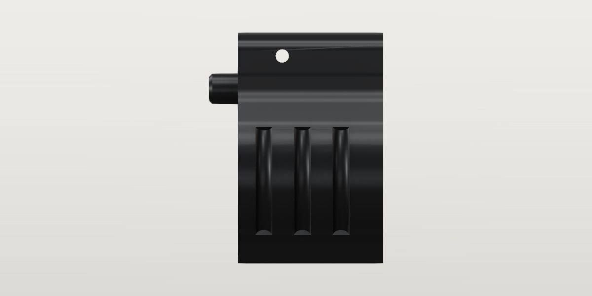
- Weight
- 1.3 oz ± 0.05 oz Confirmedpublished: SLR Rifleworks, Sentry 7 Set Screw Adjustable Gas Block (SA7-SM), Description, the maker, read Oct 28, 2026
- Lowest price
- $118.19 at SLR Rifleworks, read Nov 21, 2026 (Melonite QPQ)
- Maker's number
- SA7-SM
- Colour
- Black nitride
- Drawn as
- modelled
- Maker's page
- slrrifleworks.com
In “Two-tone 16 in, Stealth Gray and soft-shooting”, a build on the start page, as it is.
Its figures
Every figure the site draws and checks it by, with where it came from. Open one for each source's reading, and why one is used where they differ.
Bore (the journal it fits: .750 or .625)0.75 in ± 0.0005 in 19 mmConfirmedPublished: SLR Rifleworks, Sentry 7 Set Screw Adjustable Gas Block (SA7-SM), Description, the maker, read Oct 28, 2026
Published “Sentry .750" Set Screw Version - Melonite QPQ Finish” used
SLR Rifleworks, Sentry 7 Set Screw Adjustable Gas Block (SA7-SM), Description, the maker, read Oct 28, 2026 the page, harvested Oct 28, 2026
Published “Gas Seat Diameter .750”
Primary Arms, SLR Rifleworks Sentry 7 AR-15 Adjustable Gas Block - Set Screw - .750" (SA7-SM), Specifications, a seller, read Oct 28, 2026 the page, harvested Oct 28, 2026
The maker's figure; Primary Arms' specifications say the same.
The two set screws, centre to centre along the block0.4 in ± 0.0005 in 10.2 mmConfirmedPublished: SLR Rifleworks, Sentry 7 Set Screw Adjustable Gas Block (SA7-SM), Description, the maker, read Oct 28, 2026
Published “.400" Set Screw Spacing” used
SLR Rifleworks, Sentry 7 Set Screw Adjustable Gas Block (SA7-SM), Description, the maker, read Oct 28, 2026 the page, harvested Oct 28, 2026
Published “.400" set screw spacing”
Primary Arms, SLR Rifleworks Sentry 7 AR-15 Adjustable Gas Block - Set Screw - .750" (SA7-SM), Features, a seller, read Oct 28, 2026 the page, harvested Oct 28, 2026
The maker's figure; Primary Arms' page says the same.
The maker sells the same block with its front screw .450 from the rear one as another product ("Sentry 7 Set Screw Adjustable Gas Block - .450\""): "There is no difference in the blocks just the front set screw location."
The metering screw's port, fully open0.125 in ± 0.0005 in 3.2 mmConfirmedPublished: SLR Rifleworks, Sentry 7 Set Screw Adjustable Gas Block (SA7-SM), Description, the maker, read Oct 28, 2026
Published “15-position adjustability from 0 - 0.125" port opening” used
SLR Rifleworks, Sentry 7 Set Screw Adjustable Gas Block (SA7-SM), Description, the maker, read Oct 28, 2026 the page, harvested Oct 28, 2026
Inside the block, behind the adjustment screw: not drawn. 15 positions from closed to this.
Top above the bore axis0.812 in ± 0.01 in 20.6 mmConflictPhoto: US 9,410,756, sheet 3, FIG. 3: the block from its front, orthographic, 2560 x 3300 (the patent office's PDF)
Photo 0.812 in ± 0.01 in used
US 9,410,756, sheet 3, FIG. 3: the block from its front, orthographic, 2560 x 3300 (the patent office's PDF), harvested
Scale: frame from the reviewed holes top, under, right, left (648.3 px/in, rms 0.000 in over 4 points). Read by y_max of the traced outline (tools/trace.py); the outline's top: the boss's top on the bore's vertical centre line
Photo 0.848 in ± 0.012 in
SLR's own photo, DSC01311: the front face nearly square on, yawed about 20 degrees to show the right side, 2770 x 1847
Scale: the bore's opening, an ellipse fitted to the edge of the bright bore inside the black face (482.1 px tall, 452.1 wide: .750 is 642.9 px/in up the face and 602.7 across it). Read by the silhouette's top on the bore's centre column, 545 px above the bore's centre: the boss's top seen from a little above, so its far edge
The patent's front view at the journal's scale. The maker's photo reads the top 0.036 higher: it is taken from a little above (the bore's floor shows), so its silhouette's top is the boss's rear edge.
patent and photo-front differ by 0.036 in beyond what each states it is good to.
Not published. The boss's top over the gas tube. Primary Arms: "Needs a handguard with at least 1.4\" internal diameter to hide underneath".
The foot's flat below the bore's axis0.548 in ± 0.01 in 13.9 mmCorroboratedPhoto: US 9,410,756, sheet 3, FIG. 3: the block from its front, orthographic, 2560 x 3300 (the patent office's PDF)
Photo 0.548 in ± 0.01 in used
US 9,410,756, sheet 3, FIG. 3: the block from its front, orthographic, 2560 x 3300 (the patent office's PDF), harvested
Scale: frame from the reviewed holes top, under, right, left (648.3 px/in, rms 0.000 in over 4 points). Read by −y_min of the traced outline (tools/trace.py); the outline's bottom: the foot's flat
Photo 0.553 in ± 0.006 in
SLR's own photo, DSC01311: the front face nearly square on, yawed about 20 degrees to show the right side, 2770 x 1847
Scale: the bore's opening, an ellipse fitted to the edge of the bright bore inside the black face (482.1 px tall, 452.1 wide: .750 is 642.9 px/in up the face and 602.7 across it). Read by the silhouette's bottom on the bore's centre column and 120 px either side, 356 px below the bore's centre (the foot's front edge, nearest the lens)
The patent's front view at the journal's scale; the maker's photo of the product agrees within 0.005.
Not published.
Width across the ring about the bore0.899 in ± 0.01 in 22.8 mmCorroboratedPhoto: US 9,410,756, sheet 3, FIG. 3: the block from its front, orthographic, 2560 x 3300 (the patent office's PDF)
Photo 0.899 in ± 0.01 in used
US 9,410,756, sheet 3, FIG. 3: the block from its front, orthographic, 2560 x 3300 (the patent office's PDF), harvested
Scale: frame from the reviewed holes top, under, right, left (648.3 px/in, rms 0.000 in over 4 points). Read by width of the traced outline (tools/trace.py); the outline's extent across: the ring about the bore
Photo 0.872 in ± 0.02 in
SLR's own photo, DSC01311: the front face nearly square on, yawed about 20 degrees to show the right side, 2770 x 1847
Scale: the bore's opening, an ellipse fitted to the edge of the bright bore inside the black face (482.1 px tall, 452.1 wide: .750 is 642.9 px/in up the face and 602.7 across it). Read by the silhouette's edge on the part's left on the bore's row, 262.5 px from the centre across the face (0.436), twice: the front face's edge with its break, the far side of the ring
The patent's front view at the journal's scale. The maker's photo reads the left half 0.016 narrower at the front face's broken edge, inside its ±.
Not published.
The adjustment screw's axis above the bore's0.481 in ± 0.004 in 12.2 mmProvisionalPhoto: US 9,410,756 sheet 3, the patent office's PDF page 4: FIG. 3 the block from its front, FIG. 4 from its rear, orthographic, 2560 x 3300
Photo 0.481 in ± 0.004 in used
US 9,410,756 sheet 3, the patent office's PDF page 4: FIG. 3 the block from its front, FIG. 4 from its rear, orthographic, 2560 x 3300, harvested
Scale: FIG. 3's bore, a least-squares circle through its stroke (centre (1288.1, 2218.8), radius 243.1 px, rms 1.0 px), as the journal's .750: 648.3 px/in. Read by the screw's two circles in FIG. 3 (least squares through their strokes: centre (976.6, 2218.6), radii 58.4 and 45.3 px, rms 0.6): 311.5 px from the bore's centre, on its vertical centre line (0.2 px off it)
At the front face, between the bore and the boss (the instruction sheet: 'At the front of the gas block is a 15-position adjustment screw'). The maker's front view (276bd13fbaaf) has the screw's head 39 px right of the bore's centre line, which its 20 degree yaw puts on the centre line for a head standing 0.15 in out of the face.
The adjustment screw's head, diameter0.18 in ± 0.004 in 4.6 mmCorroboratedPhoto: US 9,410,756 sheet 3, the patent office's PDF page 4: FIG. 3 the block from its front, FIG. 4 from its rear, orthographic, 2560 x 3300
Photo 0.18 in ± 0.004 in used
US 9,410,756 sheet 3, the patent office's PDF page 4: FIG. 3 the block from its front, FIG. 4 from its rear, orthographic, 2560 x 3300, harvested
Scale: FIG. 3's bore, a least-squares circle through its stroke (centre (1288.1, 2218.8), radius 243.1 px, rms 1.0 px), as the journal's .750: 648.3 px/in. Read by FIG. 3's outer circle about the screw, 116.8 px across
Photo 0.186 in ± 0.01 in
SLR's own photo, DSC01311: the front face nearly square on, yawed about 20 degrees to show the right side, 2770 x 1847, harvested
Scale: the bore's opening, an ellipse fitted to its edge (482.1 px tall as .750: 642.9 px/in). Read by the head's two sides on its row, 120 px (columns 1455 and 1575)
The patent's circle; the maker's photo reads the head 0.006 larger, within its ±.
The adjustment screw's end face inside its edge break0.14 in ± 0.004 in 3.6 mmProvisionalPhoto: US 9,410,756 sheet 3, the patent office's PDF page 4: FIG. 3 the block from its front, FIG. 4 from its rear, orthographic, 2560 x 3300
Photo 0.14 in ± 0.004 in used
US 9,410,756 sheet 3, the patent office's PDF page 4: FIG. 3 the block from its front, FIG. 4 from its rear, orthographic, 2560 x 3300, harvested
Scale: FIG. 3's bore, a least-squares circle through its stroke (centre (1288.1, 2218.8), radius 243.1 px, rms 1.0 px), as the journal's .750: 648.3 px/in. Read by FIG. 3's inner circle about the screw, 90.6 px across
The adjustment screw's hex socket, across its flats0.067 in ± 0.008 in 1.7 mmProvisionalPhoto: US 9,410,756 sheet 3, the patent office's PDF page 4: FIG. 3 the block from its front, FIG. 4 from its rear, orthographic, 2560 x 3300
Photo 0.067 in ± 0.008 in used
US 9,410,756 sheet 3, the patent office's PDF page 4: FIG. 3 the block from its front, FIG. 4 from its rear, orthographic, 2560 x 3300, harvested
Scale: FIG. 3's bore, a least-squares circle through its stroke (centre (1288.1, 2218.8), radius 243.1 px, rms 1.0 px), as the journal's .750: 648.3 px/in. Read by FIG. 3's hexagon, 50 px across its corners (0.077 in) times cos 30
The tool in the box is a long hex key; no page says its size.
How far the adjustment screw's head stands out of the front face0.17 in ± 0.03 in 4.3 mmCorroboratedPhoto: SLR's own photo, DSC01311: the front face nearly square on, yawed about 20 degrees to show the right side, 2770 x 1847
Photo 0.17 in ± 0.03 in used
SLR's own photo, DSC01311: the front face nearly square on, yawed about 20 degrees to show the right side, 2770 x 1847, harvested
Scale: the bore's opening, an ellipse fitted to the edge of the bright bore inside the black face (482.1 px tall, 452.1 wide): 642.9 px/in up the face, the face turned 20.3 degrees from the lens. Read by the head's end face's middle stands 39 px to the right of the bore's centre column (1515 against 1475.6) while the patent has the screw on the centre line: 39 px over 642.9 px/in times sin 20.3 degrees
Photo 0.135 in ± 0.03 in
Primary Arms SA7-SM_00: the block from the right, ahead and above, with its roll pin and key, 2200 x 1467, harvested
Scale: an orthographic camera fitted to the photo's silhouette with the traced section (profiles.front) run along the block and the adjustment screw's head on its face, by Nelder-Mead from the best of a grid of directions: the lens toward (0.621, 0.506, 0.599) in the part frame, 543.4 px/in, IoU 0.980. Read by a cylinder of the head's diameter on the face, its length left to the same fit
Photo 0.13 in ± 0.03 in
Primary Arms SA7-SM_01: the block from the left, ahead and above, 2200 x 1467, harvested
Scale: the same fit: the lens toward (0.766, 0.482, -0.427), 738.9 px/in, IoU 0.978. Read by the same
The maker's photo turns the face by an angle its bore's ellipse gives, with no fit traded against the length; the two silhouette fits read the head shorter (their bump is the head's side as well as its end), the fitted cameras' end faces longer.
As photographed (at whatever setting each was shipped or shot at); the 15 positions' travel isn't published. The two Primary Arms photos' fitted cameras put the head's end face, where it shows in each (b5a6b18f895e at (976, 503), 8a7811f1e180 at (857, 690)), 0.20 and 0.26 in out of the face if it is on the centre line: those cameras' directions trade off against the length (see length), so their end-face readings aren't taken.
Length along the barrel0.856 in ± 0.04 in 21.7 mmConflictPhoto: Primary Arms SA7-SM_00: the block from the right, ahead and above, with its roll pin and key, 2200 x 1467
Photo 0.856 in ± 0.04 in used
Primary Arms SA7-SM_00: the block from the right, ahead and above, with its roll pin and key, 2200 x 1467, harvested
Scale: an orthographic camera fitted to the photo's silhouette with the traced section (profiles.front) run along the block and the adjustment screw's head on its face, by Nelder-Mead from the best of a grid of directions: the lens toward (0.621, 0.506, 0.599) in the part frame, 543.4 px/in, IoU 0.980. Read by the fit's own length; the next best fits (IoU within 0.002) give 0.885 and 0.916: the ± covers them
Photo 0.836 in ± 0.05 in
Primary Arms SA7-SM_01: the block from the left, ahead and above, 2200 x 1467, harvested
Scale: the same fit: the lens toward (0.766, 0.482, -0.427), 738.9 px/in, IoU 0.978. Read by the fit's own length; the next best (IoU within 0.0003) gives 0.984 with the screw's head 0.21 out, which the right photo's fit doesn't allow
Photo 0.974 in ± 0.03 in
US 9,410,756 sheet 6: FIG. 7 the block's right side, orthographic, 2560 x 3300, harvested
Scale: FIG. 7's height (905 px, the boss's top to the foot's flat) as FIG. 3's at the journal's scale (1.360 in): 665 px/in. Read by FIG. 7's two end faces, 648 px apart
The patent's embodiment, with a window through the ring where the product has three flutes: its proportions, not the product's.
Photo 0.842 in ± 0.06 in
SLR's own photo, DSC01311: the front face nearly square on, yawed about 20 degrees to show the right side, 2770 x 1847, harvested
Scale: the bore's opening, an ellipse fitted to the edge of the bright bore inside the black face (482.1 px tall, 452.1 wide): 642.9 px/in up the face, the face turned 20.3 degrees from the lens (the ellipse's axes 0.938 of one another). Read by the right side's silhouette on the bore's row (column 1016) behind the ring's widest point on the front face (column 1203.9, 0.449 in right of the bore's centre at 602.7 px/in across the face): 187.9 px, over 642.9 px/in times sin 20.3 degrees; as an orthographic view, with the lens's height taken as level (the ± covers a few degrees of it)
The right photo sees the block's length most squarely (the lens 53 degrees off its axis), and the left photo's fit and the maker's front photo agree within their ±. The patent's FIG. 7 is longer by 0.12 in, which the published weight does not allow for this section: the product is not the embodiment drawn.
photo-right and patent differ by 0.118 in beyond what each states it is good to.
photo-left and patent differ by 0.138 in beyond what each states it is good to.
patent and photo-front differ by 0.132 in beyond what each states it is good to.
Not published. The two Primary Arms photos read it through cameras fitted to their silhouettes. The weight is the check: 1.3 oz of 4140 at std.density.steel is 0.285 cubic inches, which the traced section less the bore (0.355 square inches) runs 0.80 in; the flutes and the holes take some of that back, the screws and the spring add some.
The three flutes down each side, centre to centre along the block0.227 in ± 0.02 in 5.8 mmProvisionalPhoto: Primary Arms SA7-SM_00: the block from the right, ahead and above, with its roll pin and key, 2200 x 1467
Photo 0.227 in ± 0.02 in used
Primary Arms SA7-SM_00: the block from the right, ahead and above, with its roll pin and key, 2200 x 1467, harvested
Scale: an orthographic camera fitted to the photo's silhouette with the traced section (profiles.front) run along the block and the adjustment screw's head on its face, by Nelder-Mead from the best of a grid of directions: the lens toward (0.621, 0.506, 0.599) in the part frame, 543.4 px/in, IoU 0.980. Read by each flute's middle at the ring's widest taken back through the camera onto the section's surface: 0.154, 0.387 and 0.607 in behind the front face (backproj.py); the mean of the two spacings (0.233, 0.220)
Three on each side: counted on the right side in 276bd13fbaaf and b5a6b18f895e and on the left in 8a7811f1e180. Grooves round the ring, from under the spring's flat down to the foot.
The front flute's middle behind the front face0.154 in ± 0.03 in 3.9 mmProvisionalPhoto: Primary Arms SA7-SM_00: the block from the right, ahead and above, with its roll pin and key, 2200 x 1467
Photo 0.154 in ± 0.03 in used
Primary Arms SA7-SM_00: the block from the right, ahead and above, with its roll pin and key, 2200 x 1467, harvested
Scale: an orthographic camera fitted to the photo's silhouette with the traced section (profiles.front) run along the block and the adjustment screw's head on its face, by Nelder-Mead from the best of a grid of directions: the lens toward (0.621, 0.506, 0.599) in the part frame, 543.4 px/in, IoU 0.980. Read by taken back onto the section's surface at the ring's widest (see flute_pitch)
A flute's width along the block0.106 in ± 0.02 in 2.7 mmProvisionalPhoto: Primary Arms SA7-SM_00: the block from the right, ahead and above, with its roll pin and key, 2200 x 1467
Photo 0.106 in ± 0.02 in used
Primary Arms SA7-SM_00: the block from the right, ahead and above, with its roll pin and key, 2200 x 1467, harvested
Scale: an orthographic camera fitted to the photo's silhouette with the traced section (profiles.front) run along the block and the adjustment screw's head on its face, by Nelder-Mead from the best of a grid of directions: the lens toward (0.621, 0.506, 0.599) in the part frame, 543.4 px/in, IoU 0.980. Read by the middle flute's lit wall and shadow together at the ring's widest, 45 px at the fit's 426 px/in along the block
A flute's depth into the ring0.035 in ± 0.015 in 0.9 mmProvisionalWorked out: An assumption for the drawing, not a reading: no view on file shows a flute in profile (no straight end view of the product); a third of its width, the bottom round.
Worked out 0.035 in ± 0.015 in used
An assumption for the drawing, not a reading: no view on file shows a flute in profile (no straight end view of the product); a third of its width, the bottom round., harvested
Where the flutes begin, above the bore's axis0.255 in ± 0.03 in 6.5 mmProvisionalPhoto: Primary Arms SA7-SM_00: the block from the right, ahead and above, with its roll pin and key, 2200 x 1467
Photo 0.255 in ± 0.03 in used
Primary Arms SA7-SM_00: the block from the right, ahead and above, with its roll pin and key, 2200 x 1467, harvested
Scale: an orthographic camera fitted to the photo's silhouette with the traced section (profiles.front) run along the block and the adjustment screw's head on its face, by Nelder-Mead from the best of a grid of directions: the lens toward (0.621, 0.506, 0.599) in the part frame, 543.4 px/in, IoU 0.980. Read by the three flutes' upper ends taken back onto the section's surface: 0.258, 0.248, 0.261
Where the flutes end, below the bore's axis0.38 in ± 0.05 in 9.7 mmProvisionalPhoto: Primary Arms SA7-SM_00: the block from the right, ahead and above, with its roll pin and key, 2200 x 1467
Photo 0.38 in ± 0.05 in used
Primary Arms SA7-SM_00: the block from the right, ahead and above, with its roll pin and key, 2200 x 1467, harvested
Scale: an orthographic camera fitted to the photo's silhouette with the traced section (profiles.front) run along the block and the adjustment screw's head on its face, by Nelder-Mead from the best of a grid of directions: the lens toward (0.621, 0.506, 0.599) in the part frame, 543.4 px/in, IoU 0.980. Read by the three flutes' lower ends taken back onto the section's surface: 0.328, 0.437, 0.387 (where each runs out into the foot's flank)
The roll pin's cross hole behind the front face0.262 in ± 0.05 in 6.7 mmCorroboratedPhoto: Primary Arms SA7-SM_00: the block from the right, ahead and above, with its roll pin and key, 2200 x 1467
Photo 0.262 in ± 0.05 in used
Primary Arms SA7-SM_00: the block from the right, ahead and above, with its roll pin and key, 2200 x 1467, harvested
Scale: an orthographic camera fitted to the photo's silhouette with the traced section (profiles.front) run along the block and the adjustment screw's head on its face, by Nelder-Mead from the best of a grid of directions: the lens toward (0.621, 0.506, 0.599) in the part frame, 543.4 px/in, IoU 0.980. Read by the hole's middle (735, 355) taken back onto the boss's right side
Photo 0.175 in ± 0.05 in
Primary Arms SA7-SM_01: the block from the left, ahead and above, 2200 x 1467, harvested
Scale: the same fit: the lens toward (0.766, 0.482, -0.427), 738.9 px/in, IoU 0.978. Read by the hole's middle (1130, 450) taken back onto the boss's left side
The right photo is the squarer of the two to the side the hole is on (the lens 37 degrees off the side's normal against 55); the patent's proportion, 0.268 at this length, is beside it.
The patent's FIG. 7 has it 0.305 behind the front face of a block 0.974 long.
The gas tube's hole, its axis above the bore (at the block)0.674 in ± 0.01 in 17.1 mmProvisionalPhoto: US 9,410,756 sheet 3, the patent office's PDF page 4: FIG. 3 the block from its front, FIG. 4 from its rear, orthographic, 2560 x 3300
Photo 0.674 in ± 0.01 in used
US 9,410,756 sheet 3, the patent office's PDF page 4: FIG. 3 the block from its front, FIG. 4 from its rear, orthographic, 2560 x 3300, harvested
Scale: FIG. 3's bore, a least-squares circle through its stroke (centre (1288.1, 2218.8), radius 243.1 px, rms 1.0 px), as the journal's .750: 648.3 px/in; FIG. 4 is on the same sheet at the same size (its bore 243.9 px). Read by FIG. 4's channel 6, a least-squares circle (centre (851.1, 1186.2), radius 58.6 px inside a chamfer of 64.8, rms 0.6): 436.9 px above the bore's centre
No photo on file shows the rear face. The patent's figure, 0.049 above the Army's .625 for a front sight.
The gas tube's hole, diameter0.18 in ± 0.001 in 4.6 mmConfirmedWorked out: {bcm-750-gas-block.tube_hole_d}
Worked out 0.1805 in ± 0.001 in used
{bcm-750-gas-block.tube_hole_d}
The Army's hole for the .180 tube (drawing 8448566, as the BCM block's ledger cites it). SLR: 'USES STANDARD GAS TUBE'.
Photo 0.181 in ± 0.004 in
US 9,410,756 sheet 3, the patent office's PDF page 4: FIG. 3 the block from its front, FIG. 4 from its rear, orthographic, 2560 x 3300, harvested
Scale: FIG. 3's bore, a least-squares circle through its stroke (centre (1288.1, 2218.8), radius 243.1 px, rms 1.0 px), as the journal's .750: 648.3 px/in. Read by FIG. 4's channel 6, 117.2 px across inside its chamfer
It takes the standard tube; the patent's circle is the same.
The gas tube's roll pin: its cross hole, diameter0.078 in ± 0.003 in 2 mmConfirmedWorked out: {bcm-750-gas-block.pin_hole_d}
Worked out 0.078 in ± 0.003 in used
{bcm-750-gas-block.pin_hole_d}
The Army's hole for the gas tube's pin (drawing 8448566, as the BCM block's ledger cites it): the block takes the standard tube and its pin is in the box ('Tool, roll pin and mounting screws included').
The gas tube's pin hole to its gas hole0.418 in ± 0.002 in 10.6 mmConfirmedWorked out: {bcm-750-gas-block.pin_to_port}
Worked out 0.418 in ± 0.002 in used
{bcm-750-gas-block.pin_to_port}
The Army's gas tube (drawing 8448567, as the BCM block's ledger cites it): the tube this block takes.
How far the gas tube's hole runs on ahead of the pin's hole0.217 in ± 0.015 in 5.5 mmConfirmedWorked out: {bcm-750-gas-block.tube_hole_past_pin}
Worked out 0.217 in ± 0.015 in used
{bcm-750-gas-block.tube_hole_past_pin}
Not seen: the Army's sight's depth (drawing 8448566, as the BCM block's ledger cites it), not this block's.
Its gas port ahead of its rear face0.176 in ± 0.07 in 4.5 mmProvisionalWorked out: {slr-sentry-7-gas-block.length} - {slr-sentry-7-gas-block.pin_hole_from_front} - {slr-sentry-7-gas-block.pin_to_port}
Worked out 0.176 in ± 0.07 in used
{slr-sentry-7-gas-block.length} - {slr-sentry-7-gas-block.pin_hole_from_front} - {slr-sentry-7-gas-block.pin_to_port}
Not published; the port is inside. Where the standard tube's gas hole lands with its pin in the block's cross hole. The part's frame is here.
The roll pin's cross hole, its axis above the bore0.674 in ± 0.01 in 17.1 mmConflictWorked out: {slr-sentry-7-gas-block.tube_hole_above_bore}
Worked out 0.674 in ± 0.01 in used
{slr-sentry-7-gas-block.tube_hole_above_bore}
The pin crosses the tube through the tube's own hole: at its axis.
Photo 0.699 in ± 0.03 in
Primary Arms SA7-SM_00: the block from the right, ahead and above, with its roll pin and key, 2200 x 1467, harvested
Scale: an orthographic camera fitted to the photo's silhouette with the traced section (profiles.front) run along the block and the adjustment screw's head on its face, by Nelder-Mead from the best of a grid of directions: the lens toward (0.621, 0.506, 0.599) in the part frame, 543.4 px/in, IoU 0.980. Read by the hole's middle taken back onto the boss's right side
Photo 0.717 in ± 0.03 in
Primary Arms SA7-SM_01: the block from the left, ahead and above, 2200 x 1467, harvested
Scale: the same fit: the lens toward (0.766, 0.482, -0.427), 738.9 px/in, IoU 0.978. Read by the hole's middle taken back onto the boss's left side
The pin goes through the tube; the photos, both from above, read its hole 0.03 to 0.04 higher, inside their ±.
tube and photo-left differ by 0.043 in beyond what each states it is good to.
The front set screw behind the front face0.252 in ± 0.04 in 6.4 mmProvisionalPhoto: Primary Arms SA7-SM_01: the block from the left, ahead and above, 2200 x 1467
Photo 0.252 in ± 0.04 in used
Primary Arms SA7-SM_01: the block from the left, ahead and above, 2200 x 1467, harvested
Scale: the same fit: the lens toward (0.766, 0.482, -0.427), 738.9 px/in, IoU 0.978. Read by the nearer of the two holes in the bore's floor, its middle (1030, 1100) taken back onto the bore's surface (0.366 under the axis there: the floor is 0.375)
The farther hole is half hidden by the front face's rim; its visible middle reads 0.29 behind this one, not the published .400. The rear screw is .400 behind this (SLR: 'There is no difference in the blocks just the front set screw location').
The set screws' holes, diameter0.147 in ± 0.01 in 3.7 mmCorroboratedPhoto: US 9,410,756 sheet 3, the patent office's PDF page 4: FIG. 3 the block from its front, FIG. 4 from its rear, orthographic, 2560 x 3300
Photo 0.147 in ± 0.01 in used
US 9,410,756 sheet 3, the patent office's PDF page 4: FIG. 3 the block from its front, FIG. 4 from its rear, orthographic, 2560 x 3300, harvested
Scale: FIG. 3's bore, a least-squares circle through its stroke (centre (1288.1, 2218.8), radius 243.1 px, rms 1.0 px), as the journal's .750: 648.3 px/in. Read by the hole's mouth in the bore's floor in FIG. 3, 95 px across
Photo 0.17 in ± 0.02 in
Primary Arms SA7-SM_01: the block from the left, ahead and above, 2200 x 1467, harvested
Scale: the same fit: the lens toward (0.766, 0.482, -0.427), 738.9 px/in, IoU 0.978. Read by the nearer hole's mouth across the block, 125 px at 738.9 px/in
The patent's view is square across the hole; the photo's reading is of a mouth in a curved floor, inside its ±.
The set screws' length0.15 in ± 0.03 in 3.8 mmProvisionalWorked out: An assumption for the drawing, not a reading: no page gives the screws' size; as long as the foot is deep under the bore (0.173 in) less what is left for the key, so that it ends inside the flat.
Worked out 0.15 in ± 0.03 in used
An assumption for the drawing, not a reading: no page gives the screws' size; as long as the foot is deep under the bore (0.173 in) less what is left for the key, so that it ends inside the flat., harvested
The flat spring's screw behind the front face0.771 in ± 0.04 in 19.6 mmProvisionalPhoto: Primary Arms SA7-SM_00: the block from the right, ahead and above, with its roll pin and key, 2200 x 1467
Photo 0.771 in ± 0.04 in used
Primary Arms SA7-SM_00: the block from the right, ahead and above, with its roll pin and key, 2200 x 1467, harvested
Scale: an orthographic camera fitted to the photo's silhouette with the traced section (profiles.front) run along the block and the adjustment screw's head on its face, by Nelder-Mead from the best of a grid of directions: the lens toward (0.621, 0.506, 0.599) in the part frame, 543.4 px/in, IoU 0.980. Read by the button head's middle (500, 390) taken back onto the flat (z 0.27)
SLR: 'Stamped Alloy Flat Spring with 1400deg temper' and a 'Melonite finish 4140 detent plunger': the spring is held by its screw at the rear and bears on the plunger at its front end (the patent's spring 19, screw 20 and plunger 21).
The flat spring's front end behind the front face0.094 in ± 0.03 in 2.4 mmProvisionalPhoto: Primary Arms SA7-SM_00: the block from the right, ahead and above, with its roll pin and key, 2200 x 1467
Photo 0.094 in ± 0.03 in used
Primary Arms SA7-SM_00: the block from the right, ahead and above, with its roll pin and key, 2200 x 1467, harvested
Scale: an orthographic camera fitted to the photo's silhouette with the traced section (profiles.front) run along the block and the adjustment screw's head on its face, by Nelder-Mead from the best of a grid of directions: the lens toward (0.621, 0.506, 0.599) in the part frame, 543.4 px/in, IoU 0.980. Read by the spring's rounded tip (768, 497) taken back onto the flat
The flat spring's height at its front end0.115 in ± 0.02 in 2.9 mmCorroboratedPhoto: SLR's own photo, DSC01311: the front face nearly square on, yawed about 20 degrees to show the right side, 2770 x 1847
Photo 0.115 in ± 0.02 in used
SLR's own photo, DSC01311: the front face nearly square on, yawed about 20 degrees to show the right side, 2770 x 1847, harvested
Scale: the bore's opening, an ellipse fitted to the edge of the bright bore inside the black face (482.1 px tall): 642.9 px/in up the face, which up the right side's flat (turned 70 degrees to the face, about the vertical) is the same. Read by its upper and lower edges a little behind its tip (column 1290): rows 688 and 762, 74 px
Photo 0.099 in ± 0.02 in
Primary Arms SA7-SM_00: the block from the right, ahead and above, with its roll pin and key, 2200 x 1467, harvested
Scale: an orthographic camera fitted to the photo's silhouette with the traced section (profiles.front) run along the block and the adjustment screw's head on its face, by Nelder-Mead from the best of a grid of directions: the lens toward (0.621, 0.506, 0.599) in the part frame, 543.4 px/in, IoU 0.980. Read by its upper and lower edges 0.15 in behind the tip taken back onto the flat: 0.538 and 0.439 above the bore
The maker's photo, as for the spring's height round its screw; the two readings agree within their ±.
The flat spring's screw, its button head's diameter0.12 in ± 0.02 in 3 mmProvisionalPhoto: Primary Arms SA7-SM_00: the block from the right, ahead and above, with its roll pin and key, 2200 x 1467
Photo 0.12 in ± 0.02 in used
Primary Arms SA7-SM_00: the block from the right, ahead and above, with its roll pin and key, 2200 x 1467, harvested
Scale: an orthographic camera fitted to the photo's silhouette with the traced section (profiles.front) run along the block and the adjustment screw's head on its face, by Nelder-Mead from the best of a grid of directions: the lens toward (0.621, 0.506, 0.599) in the part frame, 543.4 px/in, IoU 0.980. Read by the head's round, 65 px across where the fit's scale on the flat is 543 px/in
The flat spring's height round its screw0.198 in ± 0.02 in 5 mmCorroboratedPhoto: SLR's own photo, DSC01311: the front face nearly square on, yawed about 20 degrees to show the right side, 2770 x 1847
Photo 0.198 in ± 0.02 in used
SLR's own photo, DSC01311: the front face nearly square on, yawed about 20 degrees to show the right side, 2770 x 1847, harvested
Scale: the bore's opening, an ellipse fitted to the edge of the bright bore inside the black face (482.1 px tall): 642.9 px/in up the face, which up the right side's flat (turned 70 degrees to the face, about the vertical) is the same. Read by its upper and lower edges just ahead of its screw's head (column 1170): rows 668 and 795, 127 px
Photo 0.22 in ± 0.03 in
Primary Arms SA7-SM_00: the block from the right, ahead and above, with its roll pin and key, 2200 x 1467, harvested
Scale: the orthographic camera fitted to its silhouette (see length). Read by its upper and lower edges 0.06 ahead of its screw taken back onto the flat: 0.610 and 0.387 above the bore
The maker's photo, its scale the bore's; Primary Arms' reads it 0.02 taller through a fitted camera, inside both ±.
The flat spring's thickness0.025 in ± 0.01 in 0.6 mmProvisionalWorked out: An assumption for the drawing, not a reading: no view on file shows the spring edge on.
Worked out 0.025 in ± 0.01 in used
An assumption for the drawing, not a reading: no view on file shows the spring edge on., harvested
The flat spring's middle above the bore's axis0.515 in ± 0.03 in 13.1 mmCorroboratedPhoto: SLR's own photo, DSC01311: the front face nearly square on, yawed about 20 degrees to show the right side, 2770 x 1847
Photo 0.515 in ± 0.03 in used
SLR's own photo, DSC01311: the front face nearly square on, yawed about 20 degrees to show the right side, 2770 x 1847, harvested
Scale: the bore's opening, an ellipse fitted to the edge of the bright bore inside the black face (482.1 px tall): 642.9 px/in up the face, which up the right side's flat (turned 70 degrees to the face, about the vertical) is the same. Read by the middle of its two edges at its rear (731.5) and near its tip (725), 330.8 and 337.3 px above the bore's centre (row 1062.3); the right side stands 0.24 in off the face's plane, which a level lens doesn't move up or down
Photo 0.49 in ± 0.03 in
Primary Arms SA7-SM_00: the block from the right, ahead and above, with its roll pin and key, 2200 x 1467, harvested
Scale: an orthographic camera fitted to the photo's silhouette with the traced section (profiles.front) run along the block and the adjustment screw's head on its face, by Nelder-Mead from the best of a grid of directions: the lens toward (0.621, 0.506, 0.599) in the part frame, 543.4 px/in, IoU 0.980. Read by the middle of its edges at the front (0.538, 0.439) and the screw's middle (0.477)
The maker's photo; it puts the spring on the middle of the patent's flat (0.505), Primary Arms' through its fitted camera 0.025 lower.
The flat it lies on is the patent's (FIG. 3's outline has it on the part's right from 0.452 to 0.557 above the bore, 0.239 out from the centre line).
The edges' break0.008 in ± 0.004 in 0.2 mmProvisionalWorked out: An assumption for the drawing, not a reading: every edge in the photos shows a small break; its size isn't read.
Worked out 0.008 in ± 0.004 in used
An assumption for the drawing, not a reading: every edge in the photos shows a small break; its size isn't read., harvested
How far the flat under the spring reaches beyond the spring's edge0.012 in ± 0.008 in 0.3 mmProvisionalWorked out: An assumption for the drawing, not a reading: the spring is taller round its screw (0.198) than the patent's flat (0.105), and the photos show it lying flat on the side with a narrow lit border; the flat is drawn as far as the spring reaches and this much more.
Worked out 0.012 in ± 0.008 in used
An assumption for the drawing, not a reading: the spring is taller round its screw (0.198) than the patent's flat (0.105), and the photos show it lying flat on the side with a narrow lit border; the flat is drawn as far as the spring reaches and this much more., harvested
What it goes with
By the way it mounts, and the figures each part on file states: a part whose figures say it doesn't fit is left out, and one whose fit can't be checked from what is published is marked. A check is against published figures, not a guarantee.
Gas block journal
- Barrels
- Aero Precision 16" 5.56 CMV barrel, mid-length, BCM Standard 11.5" Carbine Barrel, Stripped, BCM Standard 14.5" Mid Length Barrel, Stripped, BCM Standard 16" Mid Length Barrel, Stripped, Bear Creek Arsenal BC-15 5.56 NATO, 16" Parkerized M4 Barrel, 1:7 Twist, Mid-Length Gas System, Daniel Defense CHF Chrome Lined 5.56 AR-15 Barrel - Carbine - Government - 10.3", Geissele Automatics CHF Chrome Lined Barrel - 5.56 - 13.9", Geissele Automatics CHF Chrome Lined Barrel - 5.56 - 14.5", Geissele Automatics CHF Chrome Lined Barrel - 5.56 - 16", Rosco Manufacturing Bloodline 10.5" M4 5.56 NATO, Rosco Manufacturing Bloodline 11.5" M4 5.56 NATO, Rosco Manufacturing Bloodline 12.5" M4 5.56 NATO
Prices on file
Each seller's latest reading of its own page: before tax and shipping, and not a quote. The pages are read again every night.
- SLR Rifleworks $118.19 Melonite QPQ Nov 21, 2026, in stock that day
- AR15Discounts $141.64 Melonite QPQ Nov 21, 2026, stock not said
- Primary Arms $148.99 Melonite QPQ Nov 21, 2026, in stock that day