Stock
Magpul MOE SL carbine stock, mil-spec
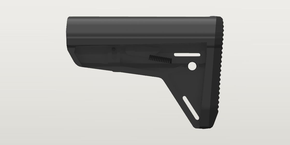
- Weight
- 9.3 oz Conflictpublished: Magpul, the maker, read Sep 30, 2026Its sources span 9.25 oz to 9.65 oz.
- Lowest price
- $62.95 at Wing Tactical, read Nov 21, 2026 (Black)
- Maker's number
- MAG347
- Colours
- Black, FDE, ODG, Stealth Gray
- Drawn as
- modelled
In “22RB .22 LR rifle”, a build on the start page, as it is.
Its figures
Every figure the site draws and checks it by, with where it came from. Open one for each source's reading, and why one is used where they differ.
Overall length7.3 in 185.4 mmConfirmedPublished: Magpul, the maker, read Sep 30, 2026
Published 7.3 in used
Magpul, the maker, read Sep 30, 2026 the page, from the project brief
Magpul: specifications assume a standard-length (flat-back) M4 carbine receiver extension.
Published “Length: 7.2"”
Primary Arms (older Magpul spec revision), a seller, read Sep 30, 2026 the page, harvested Sep 30, 2026
Magpul's earlier published figure, repeated by several retailers. Consistent with 7.3 within rounding if the true length is ~7.25 in.
Current manufacturer page.
Length of pull, collapsed10.9 in 276.9 mmConflictPublished: Magpul, the maker, read Sep 30, 2026
Published “LOP: ~10.9 in.” used
Magpul, the maker, read Sep 30, 2026 the page, from the project brief
Magpul's figure assumes their own reference rifle and trigger.
Published “Length of Pull (Collapsed): ~10.8"”
Primary Arms (older Magpul spec revision), a seller, read Sep 30, 2026 the page, harvested Sep 30, 2026
Published “LOP: ~11.1 in.”
Operation Parts, a seller, read Sep 30, 2026 the page, harvested Sep 30, 2026
Current manufacturer page. Retailers carry at least two other revisions of this figure.
spec and operation-parts differ by 0.2 in beyond what each states it is good to.
older-revision and operation-parts differ by 0.3 in beyond what each states it is good to.
Length of pull, extended14.2 in 360.7 mmConflictPublished: Magpul, the maker, read Sep 30, 2026
Published “LOP: ~14.2 in.” used
Magpul, the maker, read Sep 30, 2026 the page, from the project brief
Published “Length of Pull (Extended): ~14.1"”
Primary Arms (older Magpul spec revision), a seller, read Sep 30, 2026 the page, harvested Sep 30, 2026
Published “LOP: ~14.4 in.”
Operation Parts, a seller, read Sep 30, 2026 the page, harvested Sep 30, 2026
Current manufacturer page.
spec and operation-parts differ by 0.2 in beyond what each states it is good to.
older-revision and operation-parts differ by 0.3 in beyond what each states it is good to.
Number of positions6ConfirmedPublished: Magpul, the maker, read Sep 30, 2026
Published 6 count used
Magpul, the maker, read Sep 30, 2026 the page, from the project brief
Travel, position 1 to 63.3 in 83.8 mmConfirmedPublished: Magpul, the maker, read Sep 30, 2026
Published 3.3 in used
Magpul, the maker, read Sep 30, 2026 the page, from the project brief
Worked out 3.3 in
{.lop_extended} - {.lop_collapsed}, from the project brief
Stated directly; the LOP range agrees.
Travel per position0.66 in 16.8 mmConfirmedWorked out: {.travel} / ({.positions} - 1)
Worked out “0.66 in per step” used
{.travel} / ({.positions} - 1), from the project brief
Tube axis below the stock's top edge0.667 in 16.9 mmCorroboratedPhoto: not yet archived
Photo 0.667 in used
not yet archived, from the project brief
Scale: not recorded in brief. Read by calibrated photo measurement
Photo 0.718 in ± 0.055 in
US D736,336 S, Magpul's design patent, FIG. 7 front elevation, 300 dpi, harvested
Scale: the figure's height and width = Magpul's 5.3 and 1.7 in (307.7 px/in each, agreeing within 0.0%). Read by least-squares circle through the hidden-line bore (1.163 in across, rms 2.8 px), its centre below the outline's top; a second dashed circle (1.136 across) centres 0.054 lower, so the ± spans both
The brief's figure, which the side profile and the stock's seat were built on; Magpul's patent agrees within its ± (its bore centre reads 0.05–0.10 lower: a calibrated installed photo could settle it).
Butt behind takedown pin, position 2 (mil-spec carbine tube)9.73 in 247.1 mmProvisionalPhoto: not yet archived
Photo 9.73 in used
not yet archived, from the project brief
Scale: not recorded in brief. Read by calibrated photo measurement
Butt behind takedown pin, position 1 (mil-spec carbine tube)9.255 in ± 0.06 in 235.1 mmConflictWorked out: -{std.ar15.receiver_rear_x} + {.front_behind_receiver_pos1} + {.length}
Worked out “about 9.07 in, ±0.1 in”
{.butt_behind_pin_pos2} - {.position_step}, from the project brief
Photo 9.13 in ± 0.08 in
Aero Precision M4E1 complete lower with MOE SL, straight right side, 2000 px; supplied in chat, from the site owner
Scale: pin frame: takedown, pivot, trigger, hammer, selector (Hough-refined), 130.6 px/in, rms 0.022 in. Read by stock front edge at 1.83 in behind the takedown pin (fully collapsed), + Magpul's 7.3 in length. The butt itself is at the frame's edge, where lens compression reads the stock ~6% small, so the front edge near the pins is used
Read at a scale 2.5% too large (2026-10-05): the same five features fit the Army drawing's positions at 127.4 px/in with an rms of 0.003 in, and at that scale the front edge (column 910) is 1.92 in behind the pin before anything is allowed for the tube's silhouette standing further from the lens than the pins' heads. The reading called installed is the same photo read locally.
Worked out 9.255 in ± 0.06 in used
-{std.ar15.receiver_rear_x} + {.front_behind_receiver_pos1} + {.length}, from the site owner
The user's photo of one collapsed on a lower: the stock's front behind the receiver's rear face, read between edges an inch apart, on the Army drawing's rear face, plus Magpul's length. ± is the photo's 0.03 and the length's last digit.
Worked out 9.243 in ± 0.07 in
{bcm-receiver-extension.tube_front_behind_pin} + {bcm-receiver-extension.tube_length} - {bcm-receiver-extension.position_hole_rear_from_rear} - 5 * {bcm-receiver-extension.position_step} - {.lock_pin_behind_front} + {.length}, from the site owner
The lock pin in the tube's front hole. ± for the hole's place (0.03), the tube's seat (0.02) and the pin's (0.04), and for the tube's length, which is a generic figure.
Seated from a photo of it installed, collapsed, square from the side, read from the receiver's rear face (2026-10-05); its lock pin in the receiver extension's front hole says the same within 0.02 in, and Magpul's current lengths of pull put it 0.6 in behind the MOE Carbine, where this has it 0.56. The brief's 9.07 (a photo that isn't on file, less one step) is 0.19 in less and outside the two ±: it had the stock's front 0.05 in behind the castle nut, where the photo has 0.3 in of receiver extension showing. The first reading of the user's photo (9.13) was made at a scale 2.5% too large. Weighed against it: the brief's overall length for this build collapsed (asm.v1.oal_pos1, 30.5 in), which the build now reads 0.40 in over (30.90; 30.715 with the 9.07). It is no second witness: the brief gives it as the sum of this same butt position and a muzzle it didn't record, 0.215 in short of the muzzle since measured on the user's own upper, and no photo of the whole rifle is on file behind it.
derived and installed differ by 0.185 in beyond what each states it is good to.
derived and holes differ by 0.173 in beyond what each states it is good to.
Stock's front face behind the receiver's rear face, position 1 (collapsed)0.83 in ± 0.03 in 21.1 mmProvisionalPhoto: Aero Precision M4E1 complete lower with MOE SL, collapsed, straight right side, 2000 px; supplied in chat
Photo 0.83 in ± 0.03 in used
Aero Precision M4E1 complete lower with MOE SL, collapsed, straight right side, 2000 px; supplied in chat, from the site owner
Scale: the mid-plane's scale beside the edges read, 125 ± 2 px/in: under the pin frame's 127.4 (takedown, pivot, hammer, trigger and selector on the Army drawing's positions, rms 0.003 in: the pins' near ends, nearer the lens than the tube's silhouette) and over the 122 that the extension's 1.148 in gives across 140 px (a black tube reads thin on white); the castle nut's 173 px is 1.36 to 1.375 in, as three other makers' nuts are, at 125.8 to 127.2. Read by columns on the silhouette at the tube's top and bottom (luminance < 235) and on a 6x crop: the stock's front face 910, the receiver's rear face, where the end plate's lobe ends against it, 1013.5: 103.5 px. Both edges are in the tube's mid-plane and within 0.9 in of the frame's middle. ± is the scale's 0.013 and two edges at 1.5 px
Read locally, between edges an inch apart on the receiver extension's own silhouette, so the photo's frame doesn't enter: the receiver's rear face is the Army drawing's (std.ar15.receiver_rear_x). The same photo has 0.31 in of receiver extension showing between the castle nut and the stock (39 px), Aero's nut 0.37 in long (46.5 px) and its end plate 0.14 (18 px). It is one photo, of another maker's receiver extension than the kit's.
Lock pin behind the stock's front face2.236 in ± 0.04 in 56.8 mmProvisionalPhoto: Aero Precision M4E1 complete lower with MOE SL, collapsed, straight right side, 2000 px; supplied in chat
Photo 2.236 in ± 0.04 in used
Aero Precision M4E1 complete lower with MOE SL, collapsed, straight right side, 2000 px; supplied in chat, from the site owner
Scale: the stock's own length in the same photo, 904.5 px (its silhouette's columns 6 to 910.5) for Magpul's 7.3 in: 123.9 px/in. Read by the pin's round head (columns 620 to 643) over its track (622 to 648), centred 633: 277 px behind the front face; ± is 3 px and the length's last digit
The steel pin the latch draws out of the receiver extension's holes: its round head shows over its track, ahead of the latch's pivot. Where it stands says which hole the stock is on. The patent's bottom plan has the latch's front end round it 4.97 to 5.23 in ahead of the butt (latch_front_half_width): 2.2 behind the front.
Height5.3 in 134.6 mmConfirmedPublished: Magpul, the maker, read Sep 30, 2026
Published “Height: 5.3 in.” used
Magpul, the maker, read Sep 30, 2026 the page, harvested Sep 30, 2026
Photo “5.15–5.36 in across four side views”
a photo on file, harvested
Scale: published overall length 7.3 in (single-scale). Read by silhouette bounding-box height / width × 7.3; median of four, ± spans them
Corroborates the spec height; only checks proportions, since it's scaled from the spec length.
Published “Height: 5.26"”
Wing Tactical, a seller, read Sep 30, 2026 the page, harvested Sep 30, 2026
Manufacturer.
The latch's grip: how far out from the middle its face stands0.655 in ± 0.008 in 16.6 mmCorroboratedPhoto: US D736,336 S (Magpul), FIG. 9 bottom plan, 300 dpi; the patent office's copy
Photo 0.661 in ± 0.01 in
US D736,336 S (Magpul), FIG. 7 front elevation, 300 dpi, harvested
Scale: the front profile's scale: its height = Magpul's 5.3 in (1631 px, 307.7 px/in), its width 1.7 in across 523 px (agree). Read by each tab's outer edge from the silhouette's middle at its height: 203.5 px left and right (crop columns 75 and 482 about 278.5)
Photo 0.655 in ± 0.008 in used
US D736,336 S (Magpul), FIG. 9 bottom plan, 300 dpi; the patent office's copy, harvested
Scale: the figure's width = Magpul's 1.7 in (521 px: 306.5 px/in); its length then reads 7.24 against the published 7.3; x from the pad's rearmost row, the side outline's origin. Read by the grip's outer line, rows 1400-1660 (x 2.53-3.37), both sides: 0.653-0.656 from the middle
FIG. 9 shows each piece of the latch where it is along the stock; FIG. 7's 0.661 agrees.
The latch lies in the side pockets, a grip tab each side (FIG. 7 draws the two hatched), proud of the pocket floor and inside the stock's outline.
The latch's pivot boss: how far out from the middle its face stands0.512 in ± 0.01 in 13 mmConflictPhoto: US D736,336 S (Magpul), FIG. 9 bottom plan, 300 dpi; the patent office's copy
Photo 0.595 in ± 0.015 in
US D736,336 S (Magpul), FIG. 7 front elevation, 300 dpi, harvested
Scale: the front profile's scale: its height = Magpul's 5.3 in (1631 px, 307.7 px/in), its width 1.7 in across 523 px (agree). Read by the square boss above each tab (the pivot's head), its outer edge from the middle: 184.5 px left, 181.5 right
Photo 0.512 in ± 0.01 in used
US D736,336 S (Magpul), FIG. 9 bottom plan, 300 dpi; the patent office's copy, harvested
Scale: the figure's width = Magpul's 1.7 in (521 px: 306.5 px/in); its length then reads 7.24 against the published 7.3; x from the pad's rearmost row, the side outline's origin. Read by the outline bulges over x 4.20-4.60, where the photo's round pivot boss is (4.15-4.59): 0.509-0.515, both sides
FIG. 9 shows each piece of the latch where it is along the stock (2026-10-03). FIG. 7's 0.595 is the outermost line at that height seen from the front: the latch's front end at the lock pin, x 4.97-5.23 (latch_front_half_width), which FIG. 9 has at 0.59. The boss had been drawn 0.08 in too wide each side.
patent and plan differ by 0.083 in beyond what each states it is good to.
The latch's grip, where it ends and the arm begins, X from the butt3.46 in ± 0.03 in 87.9 mmProvisionalPhoto: US D736,336 S (Magpul), FIG. 9 bottom plan, 300 dpi; the patent office's copy
Photo 3.46 in ± 0.03 in used
US D736,336 S (Magpul), FIG. 9 bottom plan, 300 dpi; the patent office's copy, harvested
Scale: the figure's width = Magpul's 1.7 in (521 px: 306.5 px/in); its length then reads 7.24 against the published 7.3; x from the pad's rearmost row, the side outline's origin. Read by the grip's front end, chamfered in to the arm over x 3.37-3.50 (305.3 px/in along it)
The latch's arm: how far out from the middle its face stands0.477 in ± 0.01 in 12.1 mmProvisionalPhoto: US D736,336 S (Magpul), FIG. 9 bottom plan, 300 dpi; the patent office's copy
Photo 0.477 in ± 0.01 in used
US D736,336 S (Magpul), FIG. 9 bottom plan, 300 dpi; the patent office's copy, harvested
Scale: the figure's width = Magpul's 1.7 in (521 px: 306.5 px/in); its length then reads 7.24 against the published 7.3; x from the pad's rearmost row, the side outline's origin. Read by the arm's outer line, x 3.46-4.20 and 4.60-4.97: 0.471-0.485, both sides
The latch's front end, round the lock pin: how far out from the middle its face stands0.59 in ± 0.012 in 15 mmCorroboratedPhoto: US D736,336 S (Magpul), FIG. 9 bottom plan, 300 dpi; the patent office's copy
Photo 0.59 in ± 0.012 in used
US D736,336 S (Magpul), FIG. 9 bottom plan, 300 dpi; the patent office's copy, harvested
Scale: the figure's width = Magpul's 1.7 in (521 px: 306.5 px/in); its length then reads 7.24 against the published 7.3; x from the pad's rearmost row, the side outline's origin. Read by a block each side at x 4.97-5.23, from 0.40 out to 0.566-0.595 (rows 2160-2220)
Photo 0.595 in ± 0.015 in
US D736,336 S (Magpul), FIG. 7 front elevation, 300 dpi, harvested
Scale: the front profile's scale (307.7 px/in). Read by the square block above each tab: 184.5 px left, 181.5 right (the reading latch_boss_half_width had)
FIG. 9 places it along the stock; FIG. 7's agrees.
Drawn since 2026-10-13 as the lock pin's own head (lock_pin_face_half_width): FIG. 7 draws the same blocks from the front as squares 0.19 in high, which is the head's size on the side photo. The latch's hook round the pin still isn't drawn: its outline can't be told from the slot's shadow on the side photo on file.
The bore for the receiver extension, as the patent draws it1.163 in ± 0.03 in 29.5 mmProvisionalPhoto: US D736,336 S, Magpul's design patent, FIG. 7 front elevation, 300 dpi
Photo 1.163 in ± 0.03 in used
US D736,336 S, Magpul's design patent, FIG. 7 front elevation, 300 dpi, harvested
Scale: the figure's height and width = Magpul's 5.3 and 1.7 in (307.7 px/in each, agreeing within 0.0%). Read by the diameter of the least-squares circle through the hidden-line bore (rms 2.8 px, 0.009 in); ± also spans the second dashed circle the figure draws, 1.136 across
No published bore is on file for this stock, only that MAG347 is the Mil-Spec model (std.receiver_extension.milspec_od is 1.148). This is the larger of the two dashed circles tube_axis_below_top's patent reading fits; the smaller is less than the tube across and can't be what the tube passes through.
Width of the channel under the bore, for the receiver extension's indexing rail0.49 in ± 0.005 in 12.4 mmConfirmedWorked out: {std.receiver_extension.rail_width}
Worked out 0.49 in ± 0.005 in used
{std.receiver_extension.rail_width}, harvested
Not read from this stock: the mil-spec tube's rail at its own width, with nothing to spare (no clearance is known). The patent's front elevation hasn't been read for the mouth's neck.
Floor of the indexing rail's channel, below the tube axis0.874 in ± 0.005 in 22.2 mmCorroboratedWorked out: {std.receiver_extension.rail_bottom_below_axis}
Worked out 0.874 in ± 0.005 in used
{std.receiver_extension.rail_bottom_below_axis}, harvested
Not read from this stock: where the mil-spec tube's rail ends below its axis, with nothing to spare (no clearance is known).
The floors inside the frame: how far they lie in from the frame's face0.05 in ± 0.02 in 1.3 mmCorroboratedPhoto: MOE SL, straight right side view on white, 2485 px; supplied by the user from their downloads, source not recorded
Photo 0.05 in ± 0.02 in used
MOE SL, straight right side view on white, 2485 px; supplied by the user from their downloads, source not recorded, from the site owner
Scale: the side profile's own scale, 328.1 px/in: Magpul's 7.3 in length across 2413 px and 5.3 in height across 1726 px, which agree within 1.5%. Read by the shadow the frame's member casts on the triangle's floor under the QD socket (the dark line along the member's lower edge), 12 px high (0.037 in), over the light's slope: the cheek's own shadow is 94 px (0.29 in; rows 421 to 515 along column 600) under an overhang of 0.39 in (the outline's 0.85 less the web's 0.46), 0.74 in of shadow to an inch of step. ± is 4 px of shadow and the slope's
Photo 0.05 in ± 0.025 in
US D736,336 S (Magpul), FIG. 7 front elevation, 300 dpi, harvested
Scale: the front profile's scale: its height = Magpul's 5.3 in (1631 px, 307.7 px/in), its width 1.7 in across 523 px (agree); the middle is column 1665. Read by two strokes each side down the wall under the cheek, rows 1390 to 1545: the outer at 0.43 to 0.46 from the middle, which is the line the web's outline was picked on (0.46 on row 1525, where that outline begins), and an inner one at 0.385 to 0.411: 0.03 to 0.075 apart
Read on the photo the floors are outlined on; the patent's front view, read on its own, says the same.
No view on file is square across a floor. Two readings that don't share a source say about a twentieth of an inch, and it is drawn as one depth for the pocket's floors, the triangle's and the groove round the QD socket. Under the cheek the pocket has a step along it 0.37 in below the cheek's edge (rows 557 to 560 of the side photo) with a shadow 0.14 in high under it: not drawn, since which side of it stands proud isn't read.
The latch's grip: its ridges12CorroboratedPhoto: MOE SL, straight right side view on white, 2485 px; supplied by the user from their downloads, source not recorded
Photo 12 count used
MOE SL, straight right side view on white, 2485 px; supplied by the user from their downloads, source not recorded, from the site owner
Scale: a count. Read by the ridges' ends in profile along the upper edge of the grip's dark face, against the lit band over it: ten found as dark steps along a line 11 px under the grip's upper edge (27 px apart, from 6.5 to 249.5 px along it from 840,679), and two more seen on a 4x crop at columns 1113 and 1140, where the ridged edge has drawn away from that line; none in the 27 px left before the grip's front end
Photo 12 count
Magpul's gallery, FDE 03, straight left side, 1200 px, harvested
Scale: a count. Read by the dark lines across the grip's face along a line through its lower third: twelve, 9.83 px apart, columns 608.9 to 717.0
Both photos count twelve, each over the whole row.
The latch's grip: from one ridge to the next, along the grip0.082 in ± 0.002 in 2.1 mmProvisionalPhoto: MOE SL, straight right side view on white, 2485 px; supplied by the user from their downloads, source not recorded
Photo 0.082 in ± 0.002 in used
MOE SL, straight right side view on white, 2485 px; supplied by the user from their downloads, source not recorded, from the site owner
Scale: the side profile's own scale, 328.1 px/in: Magpul's 7.3 in length across 2413 px and 5.3 in height across 1726 px, which agree within 1.5%. Read by 27.0 px from ridge to ridge over nine intervals (243 px along the grip's upper edge); Magpul's left side photo has 9.9 px along the grip, the same at its own 120 px/in. ± is the scale's 1.5% and a pixel over the run
The latch's grip: its rearmost ridge, along the grip from its rear upper corner0.045 in ± 0.008 in 1.1 mmProvisionalPhoto: MOE SL, straight right side view on white, 2485 px; supplied by the user from their downloads, source not recorded
Photo 0.045 in ± 0.008 in used
MOE SL, straight right side view on white, 2485 px; supplied by the user from their downloads, source not recorded, from the site owner
Scale: the side profile's own scale, 328.1 px/in: Magpul's 7.3 in length across 2413 px and 5.3 in height across 1726 px, which agree within 1.5%. Read by the first ridge's tip 14.6 px along the upper edge from the corner the outline has at 832,680 (6.5 px along the line begun at 840,679); ± is 2.5 px
The latch's grip: how far a ridge stands from the hollow beside it0.023 in ± 0.008 in 0.6 mmProvisionalPhoto: MOE SL, straight right side view on white, 2485 px; supplied by the user from their downloads, source not recorded
Photo 0.023 in ± 0.008 in used
MOE SL, straight right side view on white, 2485 px; supplied by the user from their downloads, source not recorded, from the site owner
Scale: the side profile's own scale, 328.1 px/in: Magpul's 7.3 in length across 2413 px and 5.3 in height across 1726 px, which agree within 1.5%. Read by the scallops the ridges' ends make against the lit band, 6 to 9 px from a tip to the hollow beside it on a 4x crop; a ridge's end is rounded there, so along its length it may stand further
The latch's grip: its outer edge, from its upper face down to where the ridged face begins0.037 in ± 0.012 in 0.9 mmConflictPhoto: MOE SL, straight right side view on white, 2485 px; supplied by the user from their downloads, source not recorded
Photo 0.037 in ± 0.012 in used
MOE SL, straight right side view on white, 2485 px; supplied by the user from their downloads, source not recorded, from the site owner
Scale: the side profile's own scale, 328.1 px/in: Magpul's 7.3 in length across 2413 px and 5.3 in height across 1726 px, which agree within 1.5%. Read by the lit band between the grip's upper edge and the ridges' tips, 10 to 14 px along it
Photo 0.1 in ± 0.02 in
US D736,336 S (Magpul), FIG. 7 front elevation, 300 dpi, harvested
Scale: the front profile's scale: its height = Magpul's 5.3 in (1631 px, 307.7 px/in), its width 1.7 in across 523 px (agree); the middle is column 1665. Read by the grip's outer end each side, an upright stroke 0.635 to 0.64 from the middle from its upper face (rows 1445 to 1450) down to rows 1472 to 1480, where the hatched face turns in (0.56 on row 1490, 0.46 on row 1525): 27 to 34 px
The photo of the part as made, on which the grip is outlined; Magpul's own left side photo has the ridges to within 0.1 in of the upper edge as well. The patent's figure is a design drawing of 2014 and disagrees with the photo by more than both ±.
side and patent differ by 0.063 in beyond what each states it is good to.
On the side photo the ridges come up to a lit band 12 px high under the grip's upper edge. That band may be the grip's upper face seen from a little above (9 degrees would show it so) and not an upright edge at all; the patent draws an upright end nearly three times as high. Drawn as the photo's.
The latch's grip: how far out from the middle its ridged face ends, at its lower edge0.415 in ± 0.02 in 10.5 mmProvisionalPhoto: US D736,336 S (Magpul), FIG. 7 front elevation, 300 dpi
Photo 0.415 in ± 0.02 in used
US D736,336 S (Magpul), FIG. 7 front elevation, 300 dpi, harvested
Scale: the front profile's scale: its height = Magpul's 5.3 in (1631 px, 307.7 px/in), its width 1.7 in across 523 px (agree); the middle is column 1665. Read by the hatched face's lower edge runs down and in to the wall each side: 0.46 from the middle on row 1525, 0.426 on row 1537 and 0.411 on row 1545 (both sides alike), toward the wall's inner stroke at 0.385. The figure is the middle of what it passes over those last rows; ± spans them
The lock pin's slot: how far out from the middle its floor is0.403 in ± 0.006 in 10.2 mmConflictPhoto: US D736,336 S (Magpul), FIG. 9 bottom plan, 300 dpi; the patent office's copy
Photo 0.403 in ± 0.006 in used
US D736,336 S (Magpul), FIG. 9 bottom plan, 300 dpi; the patent office's copy, harvested
Scale: the figure's width = Magpul's 1.7 in (521 px: 306.5 px/in); the middle is column 1659.5. Read by the lock pin's block each side begins there: strokes at columns 1535.5 and 1782.5 (0.405, 0.401) along rows 2170 to 2195, the block 57.5 px long (rows 2161.5 to 2219: 0.188 in, the head's size on the side photo) and out to 0.577 to 0.595 (the reading latch_front_half_width has as 0.40 to 0.59)
Photo 0.43 in ± 0.006 in
US D736,336 S (Magpul), FIG. 7 front elevation, 300 dpi, harvested
Scale: the front profile's scale: its height = Magpul's 5.3 in (1631 px, 307.7 px/in), its width 1.7 in across 523 px (agree); the middle is column 1665. Read by the square the pin's head makes each side begins at the strokes at columns 1533.5 and 1798.0 (0.427, 0.432) along row 1372, and is out to 0.590 and 0.591; rows 1344 to 1402.5 (0.19 in)
FIG. 9 looks straight along the slot from below; in FIG. 7 the head's inner end is where it meets the wall's silhouette, which is the slot's mouth and not its floor. The two differ by more than both ±, and the difference is about the slot's depth.
plan and front differ by 0.027 in beyond what each states it is good to.
The lock pin's head: how far out from the middle its face stands0.59 in ± 0.012 in 15 mmCorroboratedWorked out: {.latch_front_half_width}
Worked out 0.59 in ± 0.012 in used
{.latch_front_half_width}, harvested
The blocks FIG. 9 draws each side at the lock pin, read here as the pin's own ends: FIG. 7 has them as squares 0.19 in high (rows 1344 to 1402.5) out to 0.590 and 0.591, FIG. 9 as blocks 0.188 in long, and the head on the side photo is 0.186 in across. The patent draws them 0.15 in lower than the photo has the head.
What it goes with
By the way it mounts, and the figures each part on file states: a part whose figures say it doesn't fit is left out, and one whose fit can't be checked from what is published is marked. A check is against published figures, not a guarantee.
Receiver extension (buffer tube)
Prices on file
Each seller's latest reading of its own page: before tax and shipping, and not a quote. The pages are read again every night.
- Wing Tactical $62.95 Black Nov 21, 2026, in stock that day
- Wing Tactical $62.95 FDE Nov 21, 2026, in stock that day
- Wing Tactical $62.95 ODG Nov 21, 2026, in stock that day
- Primary Arms $66.45 Black Nov 21, 2026, in stock that day
- Mile High Shooting Accessories $66.45 Black Nov 21, 2026, in stock that day
- Magpul $69.95 Nov 21, 2026, stock not said